Container for Transport and Storage for Compressed Natural Gas

Inactive Publication Date: 2008-06-05
DARLING CHARLES M +3
View PDF10 Cites 50 Cited by
  • Summary
  • Abstract
  • Description
  • Claims
  • Application Information

AI Technical Summary

Benefits of technology

[0016] Another embodiment of the invention is directed to methods and apparatus of storing natural gas in an underwater facility with dense phase equipment comprising: pumping the natural gas from a tanker into an underwater facility; interposing a fluid buffer between the natural gas and seawater to reduce a propensity of the seawater to mix with the natural gas; and periodically supplementing the fluid buffer with additional bu

Problems solved by technology

Also, there is an area of inherently high liner st

Method used


Image

  • Container for Transport and Storage for Compressed Natural Gas
  • Container for Transport and Storage for Compressed Natural Gas
  • Container for Transport and Storage for Compressed Natural Gas

Examples


case 3

Cylinders

[0222] The larger cylindrical vessels are closely packed in a stacked configuration, as depicted in FIGS. 13 & 14, similarly to the small cylinders.

Cylinder Vessel DesignMR60H Carbon Fiber / EpoxyMEOP = 3600 psiFS = 4.0 → Design Burst = 14400 psiLiner = MDPE, 0.25″ ThickCylinder Composite Thickness = 1.584″Helical Thickness = 0.755″Hoop Thickness = 0.829″A286 Steel End Fittings5.0″ Opening Diameter6.0″ Boss DiameterVessel Weight = 4355 lbFiber Weight = 2470 lbResin Weight = 1440 lbMDPE Weight = 403 lbsA286 Fitting Weight = 42 lbs12,060 Cylindrical Vessels (42″ Dia. × 480″ Long)5 Vertical Layers52 Staggered Rows / Layer27 Rows W / 46 Vessels26 Rows W / 45 VesselsTotal Internal Volume = 4,522,500 ft3 / 12,060 VesselsTotal Weight = 52,521,300 lb / 12,060 VesselspV / W = 2,142,640 in-lb / lb

Other Trade Considerations:

[0223] The values reported for each type of tank above represent a best-case scenario in regards to weight. Specifically, the large spherical tank is significantly (up to 30%)...

examples

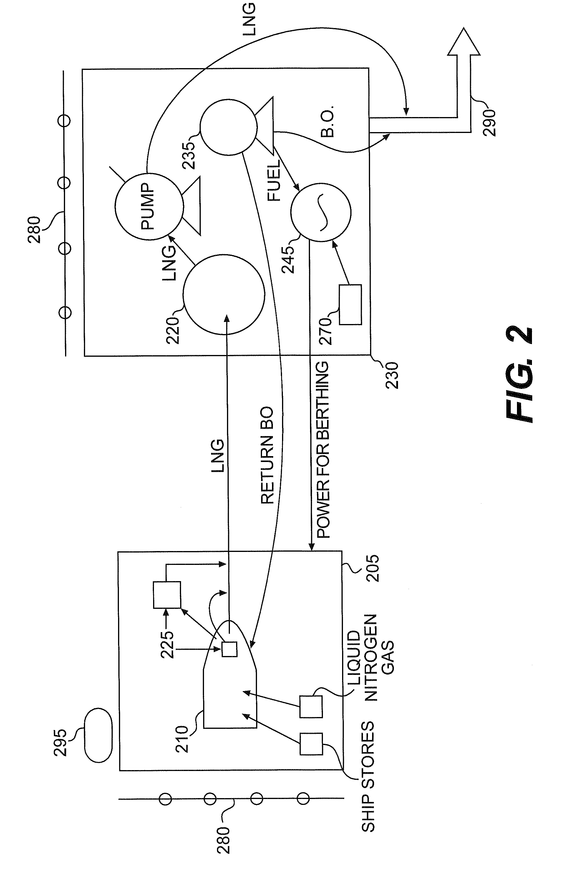
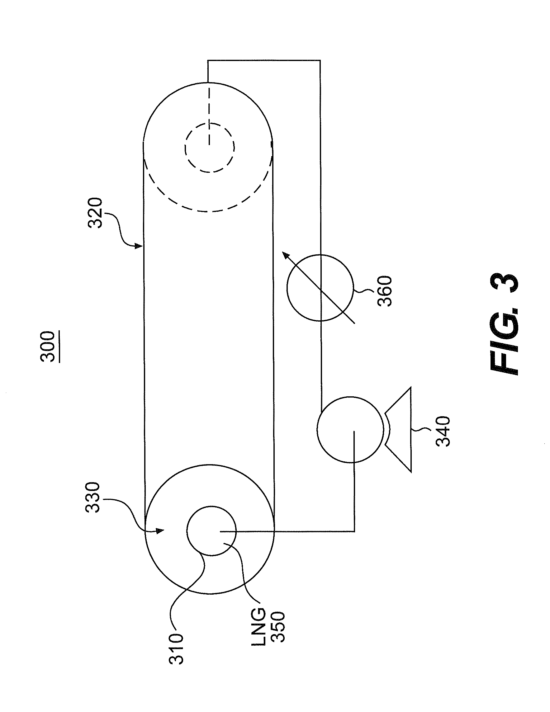
[0406]FIGS. 5 and 6 depict the use of dense phase equipment. In FIG. 5, NG is pumped from an offshore docked tanker 505 to a temporary NG tank 520 on shore. From the temporary tank, NG is pumped into an underwater cavern 540. A layer of propane is interposed by an injector / mixer 530 into the cavern as a buffer layer between the gas and the water to reduce the propensity of the water to go into the gas mixture. When desired, the NG is pumped out of the cavern, vaporized by a heater 545, and then distributed for sale through a pipeline system 590. The heater 545 and compressor 535 are optionally included for further compression. Preferably, onshore storage systems are used to mitigate the flow quantities needed to steadily supply the gas market regardless of flow variations from the offshore system operating parameters.

[0407] Preferably the gas stored in the salt cavern is natural gas, but any other hydrocarbon gas is acceptable. A method and / or apparatus is used to force gas out of ...


PUM

PropertyMeasurementUnit
Temperatureaaaaaaaaaa
Thicknessaaaaaaaaaa
Pressureaaaaaaaaaa

Abstract

A method and apparatus for unloading natural gas (NG), including gasifying liquid and/or compressed NG using the latent heat of water and propane, and/or storing liquid or compressed NG gas in a storage cavern system that utilizes a buffer layer to prevent hydrating the NG gas, the storage cavern system being configured such that the NG may be forced out of a first storage chamber by increasing the amount of brine in a second chamber to displace a buffer fluid located therein such that the displace buffer fluid enters the first storage chamber and displaces the NG, as well as the processes for compressing, chilling and/or liquefying quantities of LNG and transporting those volumes to markets for redelivery.

Description

CROSS REFERENCE TO A RELATED APPLICATION [0001] This application claims priority to Provisional Application No. 60 / 831,962 filed Jul. 20, 2006 entitled ‘Container for Transport and Storage for Compressed Natural Gas’, the contents of which are incorporated by reference in its entirety.BACKGROUND OF THE INVENTION [0002] 1. Field of the Invention [0003] This invention is directed to apparatus, systems, and methods for unloading, vaporizing, storing, and supplying natural gas in fluid form. The invention further relates to containers and transportation lines for carrying and transporting natural gas and other fluid forms. [0004] 2. Description of the Background [0005] Current systems and methods for unloading and storing natural gas (NG) are both expensive and difficult to manage. When NG is transported in bulk, other than by pipeline, it typically is in liquid form, which requires extreme refrigeration for a reduction in temperature sufficient to form a liquid. When the liquid NG (LNG...

Claims


Application Information

Patent Timeline
IPC IPC(8): F17C7/00
CPCF17C7/02F17C2270/0163F17C2221/033F17C2223/0153F17C2270/0105Y02E60/321F17C2201/0109F17C2201/0128F17C2201/032F17C2201/035F17C2201/052F17C2201/054F17C2203/0604F17C2203/0639F17C2203/0646F17C2203/0665F17C2203/067F17C2203/0673F17C2205/0184F17C2205/0329F17C2205/0355F17C2209/2154F17C2209/221F17C2221/012F17C2221/017F17C2221/035F17C2221/036F17C2223/0115F17C2223/0123F17C2223/0161F17C2223/041F17C2225/0123F17C2227/0135F17C2227/0157F17C2227/0185F17C2227/0318F17C2227/0393F17C2250/032F17C2260/017F17C2260/038F17C2260/042F17C2265/033F17C2265/05F17C2265/07F17C2270/0113F17C2270/0126F17C2270/0128F17C2270/0152F17C2209/2163Y02E60/32
Inventor DARLING, CHARLES M.FONFARA, CATHERINE M.MURRAY, A. BRUCEBARKER, KAREN D.
Owner DARLING CHARLES M
Why Eureka
Try Eureka