With the advent of ultrahigh
magnetic field (UHF) human scanners (4 T and higher), RF interactions with the
human body become a critical challenge as RF
wavelength approaches the size of the target object.
However, the transmit B1 fields generated by each coil element cannot be summed as magnitude quantities in a
single excitation because transmitting through more than one coil element involves summation of complex transmit B1 vectors.
This means that when data from different coil elements are summed as complex values (in MOS) rather than as magnitude values (in SOM), phase differences between coil elements could potentially lead to very large
signal cancellation.
First, the amount of
signal loss in the MOS relative to SOM images is large, reaching up to ˜80% in several locations.
Second, this
signal loss occurs in the periphery.
The situation becomes much more complex with a
human head, which is heterogeneous and has a complicated 3D shape that cannot be approximated with a sphere phantom.
However, the data illustrates strong, destructive B1 interferences in the periphery as well as similarities in the spatial phase patterns of the coil elements.
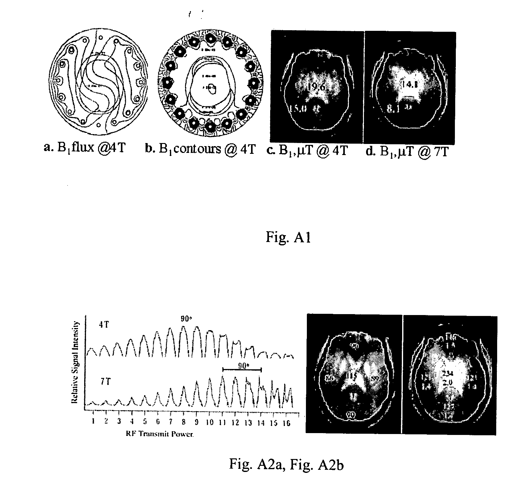
RF transmission, on the other hand, as it is used so far, becomes much more challenging because the same underlying electrodynamic mechanisms result in a much weaker B1+ in the periphery of the brain when all the elements are utilized to excite the
spins in the entire volume of the sample, as in a single volume coil.
Besides the
general pattern of peripherally weak B1 in the volume coil transmit mode, the cancellation can also be severe enough to result in very little B1+ in some regions compared to others and hence in dark spots in the image at power levels that attain maximal excitation in other regions.
Aside from hardware modification, options are limited with a single volume coil.
There are technological and physical challenges to human imaging at these
high field strengths and accompanying Larmer resonance frequencies.
These wavelengths may challenge safe and successful human scale imaging.
RF losses to the tissue conductor and the tissue
dielectric can result in severe heating for conventional pulse protocols.
The data predicted significant RF artifacts with at least one sharp line running longitudinally through the body, primarily due to destructive interference of the short (12 cm) wavelengths in the
high water content tissue dielectrics at 300 MHz.
RF non uniformities due to extremely short tissue wavelengths (9 cm) of 9.4 T (400 MHz) MRI preclude the possibility of homogeneous head images by conventional means.
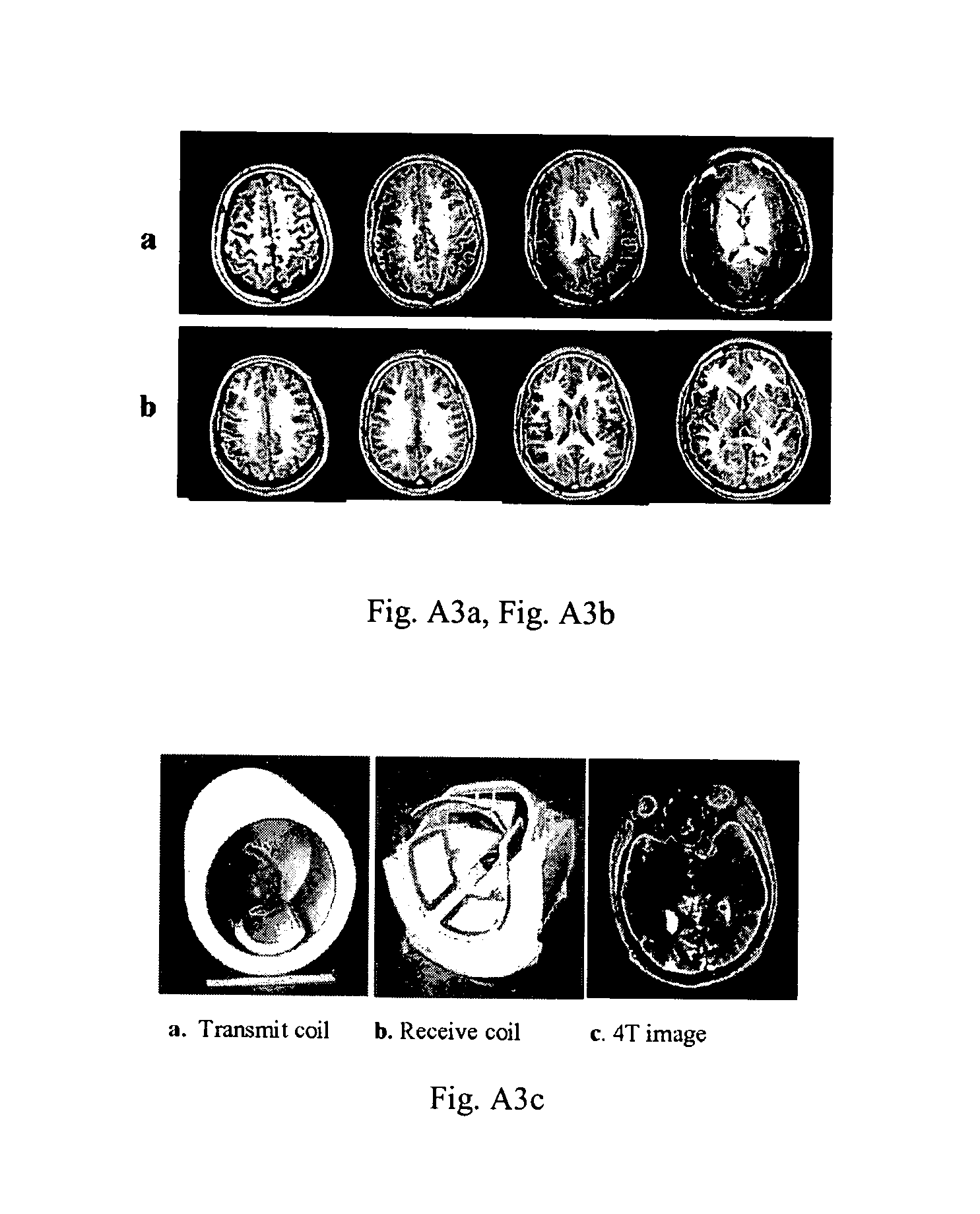
Both constructive and destructive RF interference over the whole head FOV create highly non uniform excitation and reception from a conventional, homogeneous, circularly polarized head coil.
Visible localized dark spots result from low B1+ areas due to destructive B1+ interferences.
Measure C:
Hybrid Absolute B1+ Magnitude Mapping for multiple Transmit Coils: Although useful, other solutions may not provide flattening B1+ solutions over larger spatial scales (regional / global B1 Shim), which require absolute |B1+| mapping.
In the case of multiple channel RF coils, such techniques are too
time consuming.
To expedite with low SNR for the relative measure, there will be a lot of
noise either when there is no tissue.
Ordinarily unable to measure absolute sensitivity profile of the coils.
Based on the spatial variation of the
signal intensity, it is difficult to have an
algorithm which automatically detects those edges.
Typical B1+ mapping requires about 5 minutes or more for one coil, because T1 is long, especially at high field, which is burdensome for numerous coil elements.
This can manifest itself as spurious contrast in the
MRI image due to constructive and destructive interference of B1 fields.
There are technological and physical challenges to human imaging at these high field strengths and accompanying Larmer resonance frequencies.
These wavelengths may challenge safe and successful human scale imaging.
RF losses to the tissue conductor and the tissue
dielectric can result in severe heating for conventional pulse protocols.
The data predicted significant RF artifacts with at least one sharp line running longitudinally through the body, primarily due to destructive interference of the short (12 cm) wavelengths in the
high water content tissue dielectrics at 300 MHz.
RF non uniformities due to extremely short tissue wavelengths (9 cm) of 9.4 T (400 MHz) MRI preclude the possibility of homogeneous head images by conventional means.
Both constructive and destructive RF interference over the whole head FOV create highly non uniform excitation and reception from a conventional, homogeneous, circularly polarized head coil.
Given the very small
flip angle, this bias still is limited.

