Colpitts quadrature voltage controlled oscillator

Inactive Publication Date: 2008-06-05
ELECTRONICS & TELECOMM RES INST
View PDF14 Cites 9 Cited by
  • Summary
  • Abstract
  • Description
  • Claims
  • Application Information

AI Technical Summary

Benefits of technology

[0019]The present invention is directed to a colpitts quadrature voltage controlled oscillator that is capable of obtaining a precise quadrature orthogonal sign

Problems solved by technology

However, this method results in unnecessary nonlinearity, increased phase noise, decrease in the Q-factor of an LC resonator, and increased power consumption due to the coupled transistor or the coupled transformer.
In this case, a differential voltage controlled oscillator that runs at twice the desired freq

Method used


Image

  • Colpitts quadrature voltage controlled oscillator
  • Colpitts quadrature voltage controlled oscillator
  • Colpitts quadrature voltage controlled oscillator

Examples


first exemplary embodiment

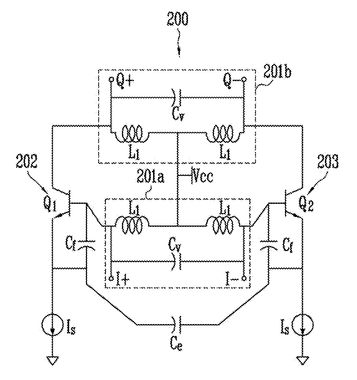
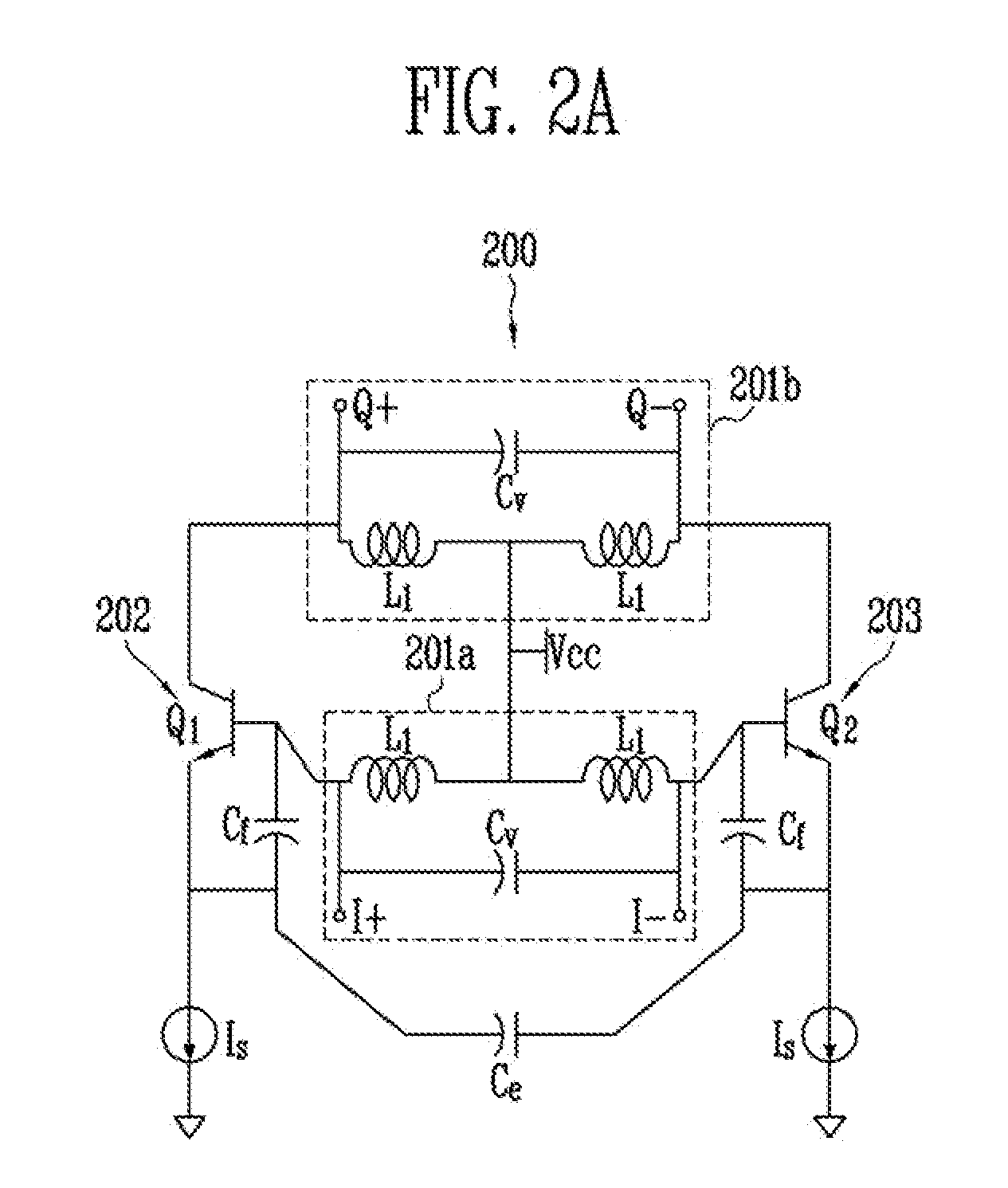
[0029]FIG. 2a is a circuit diagram of a colpitts quadrature voltage controlled oscillator 200 according to a first exemplary embodiment of the present invention.

[0030]As illustrated in FIG. 2a, the colpitts quadrature voltage controlled oscillator 200 of the present invention has a structure in which collectors of the first and second oscillation transistors Q1 and Q2 of the differential common collector colpitts voltage controlled oscillator 100 of FIG. 1a are connected to a second LC resonator 201b. The colpitts quadrature voltage controlled oscillator 200 includes first and second LC resonators 201a and 201b connected to a power supply voltage Vcc and generating a resonance frequency, first and second differential oscillators 202 and 203 including first and second oscillation transistors Q1 and Q2 that oscillate at the generated resonance frequency to output an oscillation signal, feedback capacitors Cf and a degeneration capacitor Ce connected between the first and second oscill...

second exemplary embodiment

[0043]FIG. 3a is a circuit diagram of a colpitts quadrature voltage controlled oscillator 300 according to a second exemplary embodiment of the present invention.

[0044]As illustrated in FIG. 3a, the colpitts quadrature voltage controlled oscillator 300 of the present invention has a structure in which the first LC resonator 201a of the colpitts quadrature voltage controlled oscillator 200 of FIG. 2a is combined with a negative resistance cell 301c. The colpitts quadrature voltage controlled oscillator 300 includes first and second LC resonators 301a and 301b connected to a power supply voltage Vcc and generating a resonance frequency, the negative resistance cell 301c connected to the first LC resonator 301a, first and second differential oscillators 302 and 303 including first and second oscillation transistors Q1 and Q2 that oscillate at the generated resonance frequency to output an oscillation signal, feedback capacitors Cf and a degeneration capacitor Ce connected between the f...

third exemplary embodiment

[0053]FIG. 4a is a circuit diagram of a colpitts quadrature voltage controlled oscillator 400 according to a third exemplary embodiment of the present invention.

[0054]As illustrated in FIG. 4a, the colpitts quadrature voltage controlled oscillator 400 of the present invention includes first and second LC resonators 401a and 401b connected to a power supply voltage Vcc and generating a resonance frequency, first and second differential oscillators 402 and 403 including first and second oscillation transistors Q1 and Q2 that oscillate at the generated resonance frequency to output an oscillation signal, third and fourth differential oscillators 404 and 405 including fifth and sixth oscillation transistors Q5 and Q6 that oscillate at the resonance frequency generated from the second LC resonator 401b to output an oscillation signal, feedback capacitors Cf and a degeneration capacitor Ce respectively connected between the first and second oscillation transistors Q1 and Q2 and the firth ...


PUM


Abstract

Provided is a colpitts quadrature voltage controlled oscillator capable of obtaining quadrature orthogonal signals using a quadrature combination between a base and a collector of each transistor, without using an additional circuit such as a coupled transistor, a coupled transformer, a multiphase RC filter, etc. Accordingly, since nonlinearity, increased phase noise, a decrease in the Q-factor of an LC resonator, and increased power consumption can be avoided, a colpitts quadrature voltage controlled oscillator that has low phase noise, low electric power consumption, and a compact size can be implemented.

Description

CROSS-REFERENCE TO RELATED APPLICATION[0001]This application claims priority to and the benefit of Korean Patent Application No. 2006-122523, filed Dec. 5, 2006, and No. 2007-57596, filed Jun. 13, 2007, the disclosure of which is incorporated herein by reference in its entirety.BACKGROUND[0002]1. Field of the Invention[0003]The present invention relates to a colpitts quadrature voltage controlled oscillator, and more particularly, to a colpitts quadrature voltage controlled oscillator that is capable of obtaining a precise quadrature orthogonal signal without using a separate coupled device or a passive / active device, has low phase noise, consumes less electric power, and is compact in size.[0004]2. Discussion of Related Art[0005]Currently, telecommunication transceiver systems are switching from a super-heterodyne architecture to a direct conversion architecture, which has several advantages in terms of circuit structure, power consumption, and cost.[0006]In a direct conversion tra...

Claims


Application Information

Patent Timeline
IPC IPC(8): H03B27/00H03B5/12
CPCH03B5/1231H03B2200/0078H03B2200/0074H03B5/1218
Inventor LEE, JA YOLLEE, SANG HEUNGYU, HYUN KYU
Owner ELECTRONICS & TELECOMM RES INST
Why Eureka
Try Eureka