Matching circuit and multi-band amplifier

Inactive Publication Date: 2008-06-05
NTT DOCOMO INC
View PDF5 Cites 39 Cited by
  • Summary
  • Abstract
  • Description
  • Claims
  • Application Information

AI Technical Summary

Benefits of technology

[0015]An object of the present invention is to provide a matching circuit efficiently operating for signals of multiple frequency

Problems solved by technology

In the method in which amplifiers including amplification devices and matching circuits are provided as many as frequency bands to be used and the amplifiers are switched according to a used frequency, it is necessary to provide different amplifiers for the respective frequency bands to be used, resulting in a large circuit size.
However, when using a matching circuit designed for a wide band, it is difficult to optimally design the matching circuit for used frequency bands.
Particularly, problems arise in the design o

Method used


Image

  • Matching circuit and multi-band amplifier
  • Matching circuit and multi-band amplifier
  • Matching circuit and multi-band amplifier

Examples


first embodiment

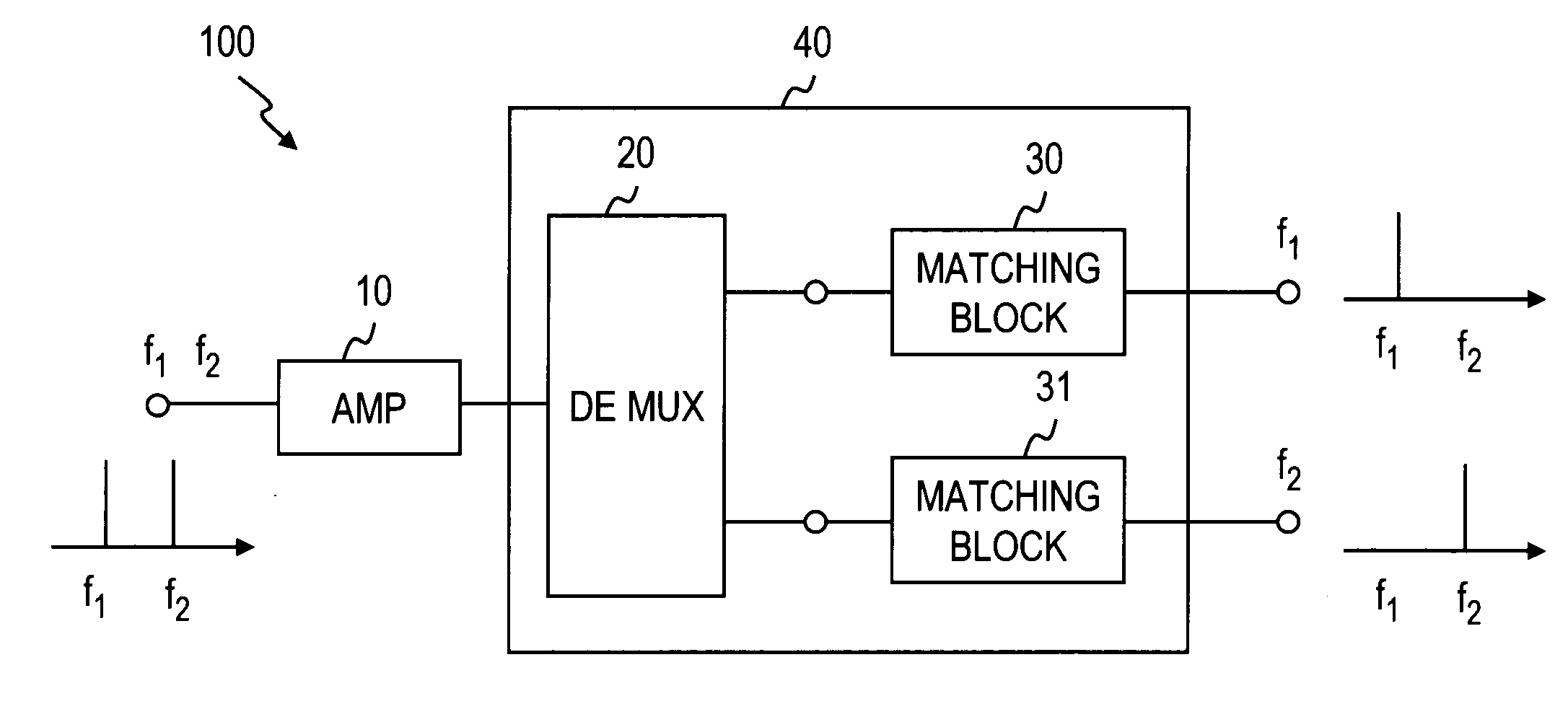
[0051]FIG. 4 shows an embodiment of an output-side circuit of a multi-band amplifier. A matching circuit of the present invention is provided on the output side of an amplification device of the multi-band amplifier, so that a power amplifier can be designed with high efficiency and high performance. A multi-band amplifier 100 shown in FIG. 4 amplifies signals of two frequency bands f1 and f2. The multi-band amplifier 100 is made up of an amplification device 10 and a matching circuit 40. The matching circuit 40 is made up of a demultiplexer 20, a matching block 30, and a matching block 31.

[0052]The amplification device 10 is fed with a combined signal of the signal of the first frequency band f1 and the signal of the second frequency band f2. The amplification device 10 amplifies the inputted signal and outputs the amplified signal to the demultiplexer 20. The demultiplexer 20 demultiplexes the signal having been amplified by the amplification device 10 into the signal of the frequ...

second embodiment

[0096]In the first embodiment, the matching circuits and the multi-band amplifiers are disposed on the output side. A similar matching circuit may be used on the input side of a multi-band amplifier. By disposing the matching circuit of the present invention on the input side, an amplifier can be designed with high efficiency. In the following explanation, the same parts as those of the first embodiment are indicated by the same reference numerals and the explanation thereof is omitted.

[0097]FIG. 18 shows an example of a multi-band amplifier in which the matching circuit of the first embodiment is used on the input side of the multi-band amplifier. A multi-band amplifier 500 shown in FIG. 18 amplifies the signals of two frequency bands f1 and f2. The multi-band amplifier 500 is made up of an amplification device 10 and a matching circuit 501. The matching circuit 501 includes, for example, a multiplexer 60, a matching block 530, and a matching block 531.

[0098]Of the input signals of...

third embodiment

[0103]A multi-band amplifier of a third embodiment is obtained by combining the matching circuit and the amplification device of the first embodiment and the matching circuit of the second embodiment. For example, a multi-band amplifier 600 shown in FIG. 19 includes a matching circuit 501 described in the second embodiment, the amplification device 10 for amplifying a signal outputted from the matching circuit 501, and the matching circuit 40 for performing, for each frequency band, impedance matching on a signal outputted from the amplification device 10 in the first embodiment.

[0104]The configurations and functions of the parts are similar to those of the first and second embodiments. Thus the same parts are indicated by the same reference numerals and the explanation thereof is omitted. As in the first and second embodiments, the matching circuit 501 and the matching circuit 40 can be configured for multiple bands and may include the demultiplexer 20, the multiplexer 60, the isol...


PUM


Abstract

A matching circuit includes a demultiplexer for demultiplexing a signal outputted from an amplification device into signals of respective frequency bands, and at least two matching blocks which are connected to the demultiplexer, are respectively fed with the signals of the respective frequency bands, and perform impedance matching in the respective frequency bands of the inputted signals. Impedance matching is performed on each of the demultiplexed signals of the respective frequency bands, thereby achieving a matching circuit capable of efficiently performing impedance matching in the respective frequency bands. With this matching circuit, it is possible to achieve a multi-band amplifier capable of simultaneously amplifying signals of multiple frequency bands with high efficiency and low noise.

Description

TECHNICAL FIELD[0001]The present invention relates to a matching circuit for obtaining impedance matching between an amplification device and a peripheral circuit thereof to efficiently perform amplification. The present invention also relates to multi-band amplifiers which are capable of amplifying signals of multiple frequencies one by one or at the same time.BACKGROUND ART[0002]The diversification of radio communication service has increased demand for multi-band radio sets for processing signals of multiple frequency bands. In radio sets, an absolutely necessary device is a power amplifier. For efficient amplification, it is necessary to obtain impedance matching between an amplification device for amplifying a signal and a peripheral circuit of the device. Matching circuits are used for this purpose. Here, the input / output impedances of the peripheral circuit are generally set at a fixed value. Hereinafter, the input / output impedance of the peripheral circuit will be referred t...

Claims


Application Information

Patent Timeline
IPC IPC(8): H03H7/38H03F3/60
CPCH03F1/0288H03F1/56H03F3/602H04B1/0458H03F2200/423H04B1/0057H03F2200/111H03H11/28
Inventor FUKUDA, ATSUSHIOKAZAKI, HIROSHINARAHASHI, SHOICHI
Owner NTT DOCOMO INC
Why Eureka
Try Eureka