Wireless Security System

Inactive Publication Date: 2008-06-05
THE CHAMBERLAIN GRP INC
View PDF68 Cites 16 Cited by
  • Summary
  • Abstract
  • Description
  • Claims
  • Application Information

AI Technical Summary

Benefits of technology

[0008]It is a further object and advantage of the present invention to provide a system for monitoring and controlling secure points of entry and access points that is easily installed.
[0009]It is an additional object and advantage of the present invention to provide a system for monitoring and controlling secure points of entry and access points.
[0010]It is also object and advantage of the present invention to provide a system for monitoring and controlling secure points of entry and access points that that is less costly.
[0011]It is another object and advantage of the present invention to provide a system for monitoring and controlling secure points of entry and access points that works with existing systems and hardware.
[0012]In accordance with the foregoing objects and advantages, the present invention provides a system for managing secure access points comprising a wireless transceiver associated with each monitoring device located at the points of entry and access points that communicates with a central transceiver located at a control center. Each wireless transceiver located at the entry or acces

Problems solved by technology

In the case of new construction, the wiring for the system and the labor associated with installation can be very costly.
In existing buildings or structures, installation of the necessary wiring may be even more costly, due to the additional requirement the

Method used


Image

  • Wireless Security System
  • Wireless Security System
  • Wireless Security System

Examples


Example

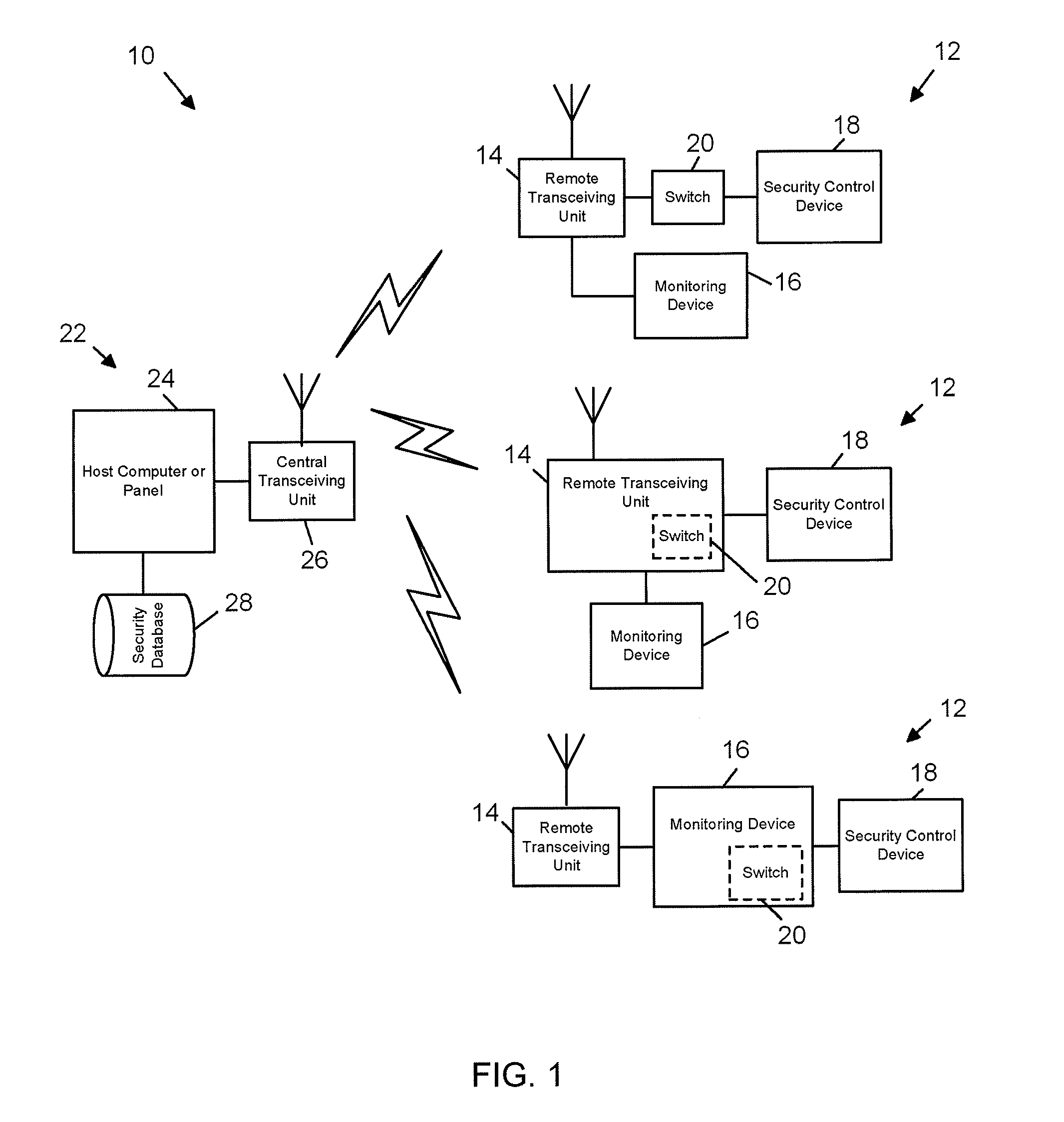
[0019]Referring now to the drawings, wherein like reference numerals refer to like parts throughout, there is seen in FIG. 1 a wireless security system 10 according to the present invention. System 10 generally comprises any number of remote locations 12, each of which preferably includes a remote transceiver unit 14, a monitoring device 16 interconnected to the remote transceiver unit 14, and a point of entry or access security control device 18 interconnected to remote transceiver unit 14 and / or monitoring device 16. Monitoring device 16 accepts data indicative of a user attempting to gain access, and thus may comprise keypad, an identification card reader, a remote receiver (such as an radiofrequency or infrared receiver), a biometric reader, such as a fingerprint or retina scanner, or other device that receive an input of data from user, whether in the form of direct data entry or a signal. Access control device 18 may comprise an electric door strike, or any other electrically ...


PUM


Abstract

A wireless system for granting or denying access to protected location or equipment and providing compatibility with existing access point devices and control equipment. The system is based on a remote wireless unit positioned at each protected location and interfaced with security hardware at the location, such as a keypad. The remote unit is provided access to the data entered by a user trying to gain access, packaged with an electronic location identification code, and wirelessly transmitted to a central unit. The central unit is interfaced with a central computer and interprets the location identification code. The central computer may then determine whether or not to grant access based on the data entered at the remote location and the location identification provided by the remote unit. The central unit then transmits the determination back to the remote location along with the identification code. The remote unit provides the determination to the security hardware if the location code is applicable.

Description

BACKGROUND OF THE INVENTION[0001]1. Field of the Invention[0002]The present invention relates to access control systems and, more particularly, to a system for wirelessly controlling access to multiple remote locations.[0003]2. Description of the Related Art[0004]Conventional systems for securely monitoring and controlling points of entry and access points generally require the placement of a monitoring device, such as a password accepting keypad, security card reader, or locking mechanism, at every possible point of entry or point of access that is to be secured by the system. Each monitoring device is interconnected to central database or control center via wires extending from the monitoring device through the building or enclosure to the control center. The wires are typically routed through an access panel at the control center having an input / output port for each location secured by the monitoring device. The conventional method of electrically wiring all of the monitoring dev...

Claims


Application Information

Patent Timeline
IPC IPC(8): G08C19/00G08C19/16H04B1/00
CPCG08C17/02
Inventor NASSIMI, SHARY
Owner THE CHAMBERLAIN GRP INC
Why Eureka
Try Eureka