
Hybrid random bead/chip based microarray

a microarray and random bead technology, applied in the field of optical identification, can solve the problems of limited number of identifiable codes in the current bead technology, not as flexible or economically customizable as beads,

Active Publication Date: 2008-06-05
ILLUMINA INC
View PDF69 Cites 24 Cited by
  • Summary
  • Abstract
  • Description
  • Claims
  • Application Information

AI Technical Summary

Benefits of technology

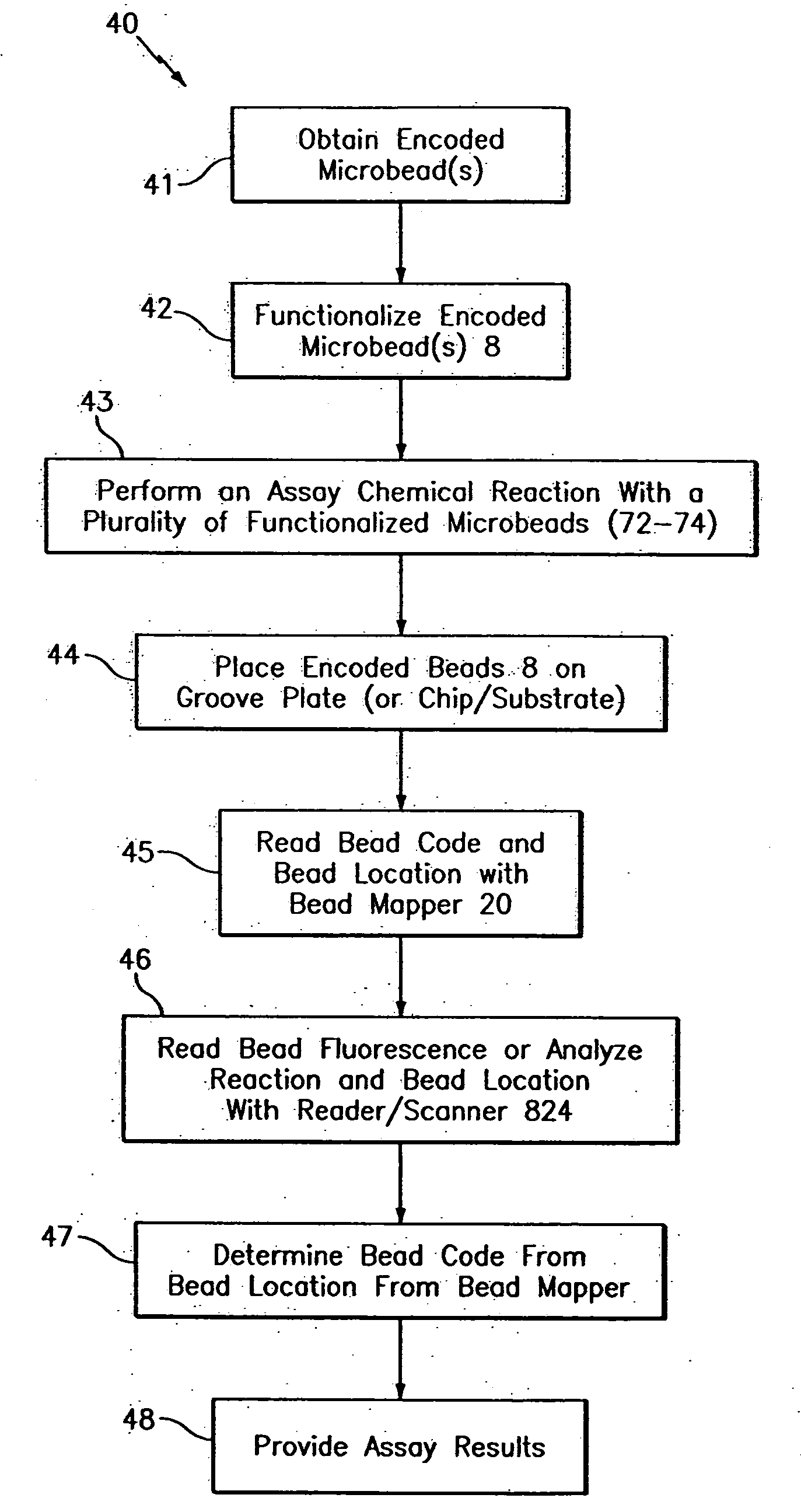
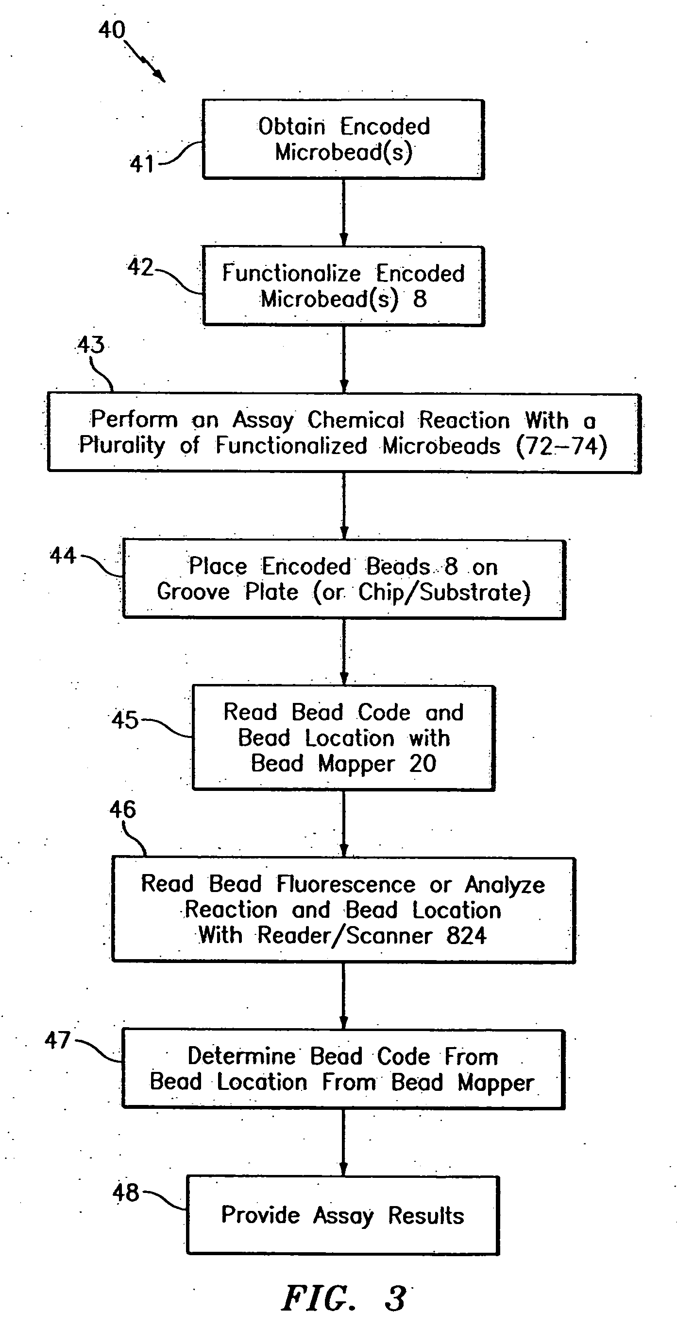
[0017]This self-assembled “chip” approach has many advantages over conventional bead based assays. In particular, since the beads are fixed on a chip substrate (e.g., groove plate), they may be examined and re-examined at any time. Also, beads of interest can be easily removed and sorted from the plate / chip after an experiment is performed. More specifically, after reading the chip, the beads may be removed from the chip for further and / or alternative processing or experiments. If desired, the chip substrate and / or the beads may be reused in other experiments or assays. Further, a fixed plate format is easier to use in experiments that vary the temperature. Still further, a fixed plate format allows convenient use of a standard chip reader to examine the beads. Also, the beads do not need to be examined using a flow cytometer.
[0019]The microbeads are inexpensive to manufacture and the identification codes are easy and inexpensive to imprint into the microbeads. The codes are digitally readable and easily adapted to optical coding techniques. Thus, the bead mapper optical readout is very simple and inexpensive to implement. Further, the invention allows for the use of a standard scanner to the label used for the analyte, which may avoid the need to purchase an additional scanner.

Problems solved by technology

The beads have the advantage of using liquid or solution based chemistry and flexibility but current bead technology does have a limited number of identifiable codes and / or are not suitable for harsh environments / chemicals.
Whereas chips typically have the advantage of having higher density (or high multiplexing) capability than beads and can be read using standard fluorescence scanners, but are not as flexible or economically customizable as beads.

Method used


Image

  • Hybrid random bead/chip based microarray
  • Hybrid random bead/chip based microarray
  • Hybrid random bead/chip based microarray

Examples


Embodiment Construction

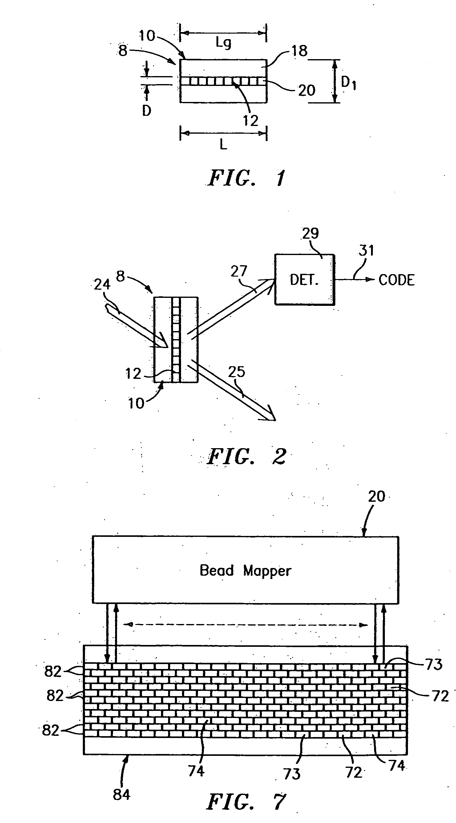
[0079]Referring to FIG. 1, a hybrid random bead / chip based microarray includes a diffraction grating-based optical identification element 8 (or encoded element or coded element) which comprises a known optical substrate 10, having an optical diffraction grating 12 disposed (or written, impressed, embedded, imprinted, etched, grown, deposited or otherwise formed) in the volume of or on a surface of a substrate 10. The grating 12 is a periodic or aperiodic variation in the effective refractive index and / or effective optical absorption of at least a portion of the substrate 10.

[0080]The optical identification element 8 described herein is similar to that described in Copending U.S. patent applications, Ser. No. 10 / 661,234, filed Sep. 12, 2003, entitled “Diffraction Grating-Based Optical Identification Element”, which is incorporated herein by reference in its entirety.

[0081]In particular, the substrate 10 has an inner region 20 where the grating 12 is located. The inner region 20 may b...


PUM

PropertyMeasurementUnit
lengthaaaaaaaaaa
refractive index n1aaaaaaaaaa

Abstract

A method and apparatus for performing an assay process, featuring providing microbeads in a solution, each microbead having a particle substrate with a grating with a superposition of different predetermined regular periodic variations of the index of refraction disposed in the particle along a grating axis and indicative of a code; placing the microbeads on an alignment substrate; reading codes of the microbeads and the position thereof on the alignment substrate; reading the fluorescence on each microbead and the position order thereof on the alignment substrate; and determining an assay result based on bead position order and bead code of the earlier reading steps.

Description

CROSS-REFERENCE TO RELATED APPLICATIONS [0001]This application claims benefit to patent application Ser. No. 10 / 763,995, issued as U.S. Pat. No. 7,164,533, which is hereby incorporated by reference in its entirety. U.S. Pat. No. 7,164,533 claims the benefit of U.S. Provisional Patent Applications, Ser. No. 60 / 441,678, filed Jan. 22, 2003, entitled “Hybrid Random Bead / Chip Microarray”, and Ser. No. 60 / 519,932, filed Nov. 14, 2003, entitled, “Diffraction Grating-Based Encoded Microparticles for Multiplexed Experiments”, and is a continuation-in-part of U.S. patent applications, Ser. No. 10 / 661,234, filed Sep. 12, 2003, entitled “Diffraction Grating-Based Optical Identification Element”; Ser. No. 10 / 661,031, filed Sep. 12, 2003, entitled “Diffraction Grating-Based Encoded Micro-Particles for Multiplexed Experiments”; and Ser. No. 10 / 661,836, filed Sep. 12, 2003, entitled “Method and Apparatus for Aligning Microbeads in order to Interrogate the Same”, of which all the foregoing are inco...

Claims


Application Information

Patent Timeline
Patent Type & Authority Applications(United States)
IPC IPC(8): G01J3/02B01J19/00G01N33/543G01N33/552G02B5/18G02B6/34G03H1/00G06K19/00G06K19/06G06T5/00G06V30/224
CPCG01N21/4788G06K19/06009G01N21/645G01N21/6452G01N21/7743G01N33/54306G01N33/54313G01N33/54366G01N33/54386G01N33/552G03H1/0005G03H1/02G03H1/0236G03H1/26G03H2001/0033G03H2001/0044G03H2210/53G03H2210/63G03H2230/10G03H2250/12G06K19/04G01N21/6428
Inventor MOON, JOHNKERSEY, ALAN D.PUTNAM, MARTIN A.LI, TUO
Owner ILLUMINA INC
Learn More