Hybrid random bead/chip based microarray

Active Publication Date: 2007-01-16
CYVERA CORP
View PDF213 Cites 102 Cited by
  • Summary
  • Abstract
  • Description
  • Claims
  • Application Information

AI Technical Summary

Benefits of technology

[0012]Objects of the present invention include provision of a platform tha

Problems solved by technology

The beads have the advantage of using liquid or solution based chemistry and flexibility but current bead technology does have a limited number of identifiable codes and/or are not suitable for harsh environments/chemicals.
Whe

Method used


Image

  • Hybrid random bead/chip based microarray
  • Hybrid random bead/chip based microarray
  • Hybrid random bead/chip based microarray

Examples


Embodiment Construction

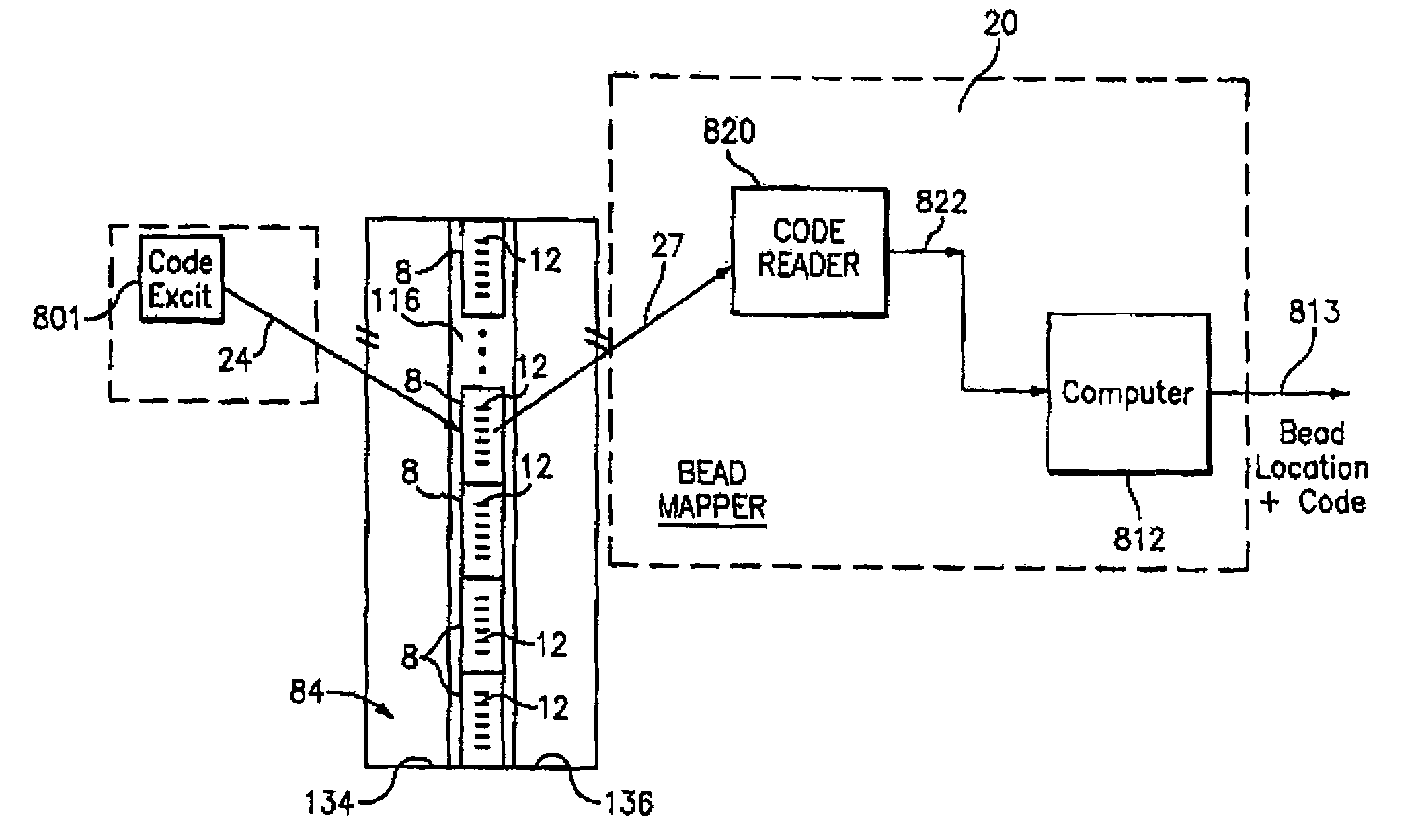
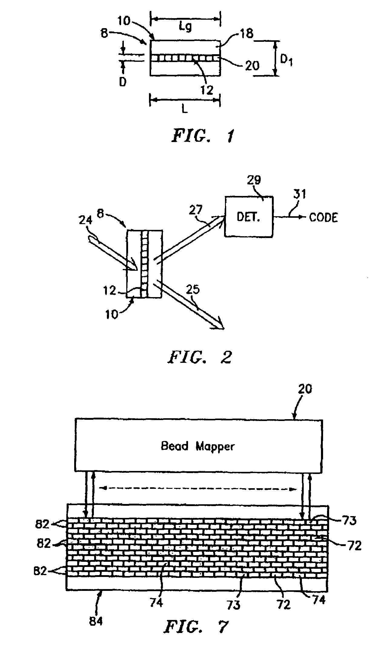
[0079]Referring to FIG. 1, a hybrid random bead / chip based microarray includes a diffraction grating-based optical identification element 8 (or encoded element or coded element) which comprises a known optical substrate 10, having an optical diffraction grating 12 disposed (or written, impressed, embedded, imprinted, etched, grown, deposited or otherwise formed) in the volume of or on a surface of a substrate 10. The grating 12 is a periodic or a periodic variation in the effective refractive index and / or effective optical absorption of at least a portion of the substrate 10.

[0080]The optical identification element 8 described herein is similar to that described in Copending U.S. patent application Ser. No. 10 / 661,234, filed Sep. 12, 2003, entitled “Diffraction Grating-Based Optical Identification Element”, which is incorporated herein by reference in its entirety.

[0081]In particular, the substrate 10 has an inner region 20 where the grating 12 is located. The inner region 20 may be...


PUM


Abstract

A method and apparatus f or performing an assay process, featuring providing microbeads in a solution; placing the microbeads on an alignment substrate; reading codes of the microbeads and the position thereof on the alignment substrate; reading the fluorescence on each microbead and the position order thereof on the alignment substrate; and determining an assay result based on bead position order and bead code of the earlier reading steps, where the microbead is an encoded particle having a particle substrate; a portion of the substrate being made of a substantially single material and having at least one diffraction grating embedded therein, the grating having a resultant refractive index variation within the single material at a grating location; and the grating providing an optical output signal indicative of a code when illuminated by an incident light signal propagating from outside said substrate, the optical output signal being a result of passive, non-resonant scattering from said grating when illuminated by said incident light signal.

Description

CROSS-REFERENCE TO RELATE APPLICATIONS[0001]This application claims the benefit of U.S. Provisional Patent Applications, Ser. No. 60 / 441,678, filed Jan. 22, 2003, entitled “Hybrid Random Bead / Chip Microarray”, and Ser. No. 60 / 519,932, filed Nov. 14, 2003, entitled, “Diffraction Grating-Based Encoded Microparticles for Multiplexed Experiments”, and is a continuation-in-part of U.S. patent application Ser. No. 10 / 661,234, filed Sep. 12, 2003, entitled “Diffraction Grating-Based Optical Identification Element”; Ser. No. 10 / 661,031, filed Sep. 12, 2003, entitled “Diffraction Grating-Based Encoded Micro-Particles for Multiplexed Experiments”; and Ser. No. 10 / 661,836, filed Sep. 12, 2003, entitled “Method and Apparatus for Aligning Microbeads in order to Interrogate the Same”, of which all the foregoing are incorporated herein by reference in their entirety.[0002]U.S. patent applications Ser. Nos. 10 / 661,082, . . . , 10 / 661,254 and 10 / 661,116, filed Sep. 12, 2003, contain subject matter r...

Claims


Application Information

Patent Timeline
IPC IPC(8): G02B5/18B01J19/00G01N33/543G01N33/552G02B6/34G03H1/00G06K19/00G06K19/06G06T5/00G06V30/224
CPCG01N21/4788G06K19/06009G01N21/645G01N21/6452G01N21/7743G01N33/54306G01N33/54313G01N33/54366G01N33/54386G01N33/552G03H1/0005G03H1/02G03H1/0236G03H1/26G06K19/04G01N21/6428G03H2001/0033G03H2001/0044G03H2210/53G03H2210/63G03H2230/10G03H2250/12
Inventor MOON, JOHNKERSEY, ALAN D.PUTNAM, MARTIN A.LI, TUO
Owner CYVERA CORP
Why Eureka
Try Eureka