Solid state optical scanners based on electro-optic graded index

Inactive Publication Date: 2008-06-05
CRYSTAL RES
View PDF3 Cites 12 Cited by
  • Summary
  • Abstract
  • Description
  • Claims
  • Application Information

AI Technical Summary

Benefits of technology

[0006]One aspect of this invention is to use optical transparent crystals that composed of materials with graded electro-optic effect. The material of the graded electro-optic effect has a characteristic that the electro-optic coefficient varies gradually or step-by-step along the direction of applied electric field. As a result, the electro-optic index modulation changes gradually or step-by-step inside the crystal under applied electric field.
[0007]Another aspect of this invention is to implement an optical beam control by applying an electric signal to an electro-optic crystal composed of a material that has graded electro-optic effect to provide high-speed, wide-angle beam scanning using low driving voltage such that the above-discussed difficulties and limitations can b

Problems solved by technology

Current beam steering systems are very complex, costly, and too large for most applications due to the required space for placement of the steering systems.
Devices for controlling the direction of an optical beam have been limited in the past, and confined almost entirely to such methods as galvanic mirrors.
The optical steering systems that implement these methods have been limited by various problems including scanning speed, driving power, and resolution of beam control.
More complex and costly fabrication and assembling proces

Method used


Image

  • Solid state optical scanners based on electro-optic graded index
  • Solid state optical scanners based on electro-optic graded index
  • Solid state optical scanners based on electro-optic graded index

Examples


Embodiment Construction

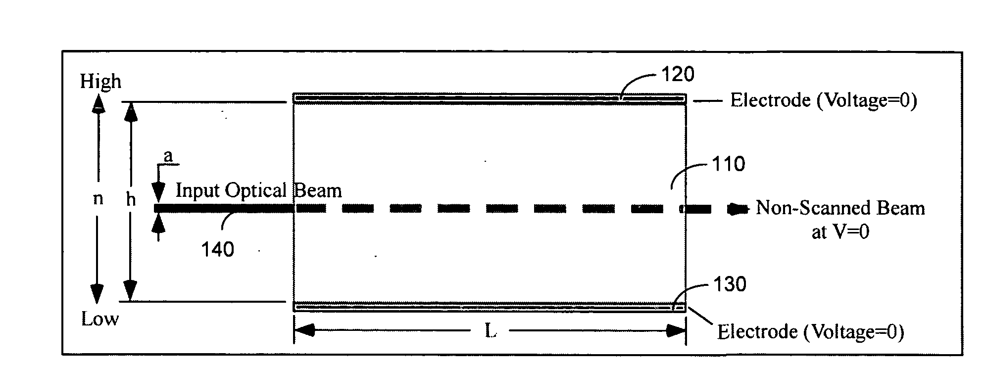
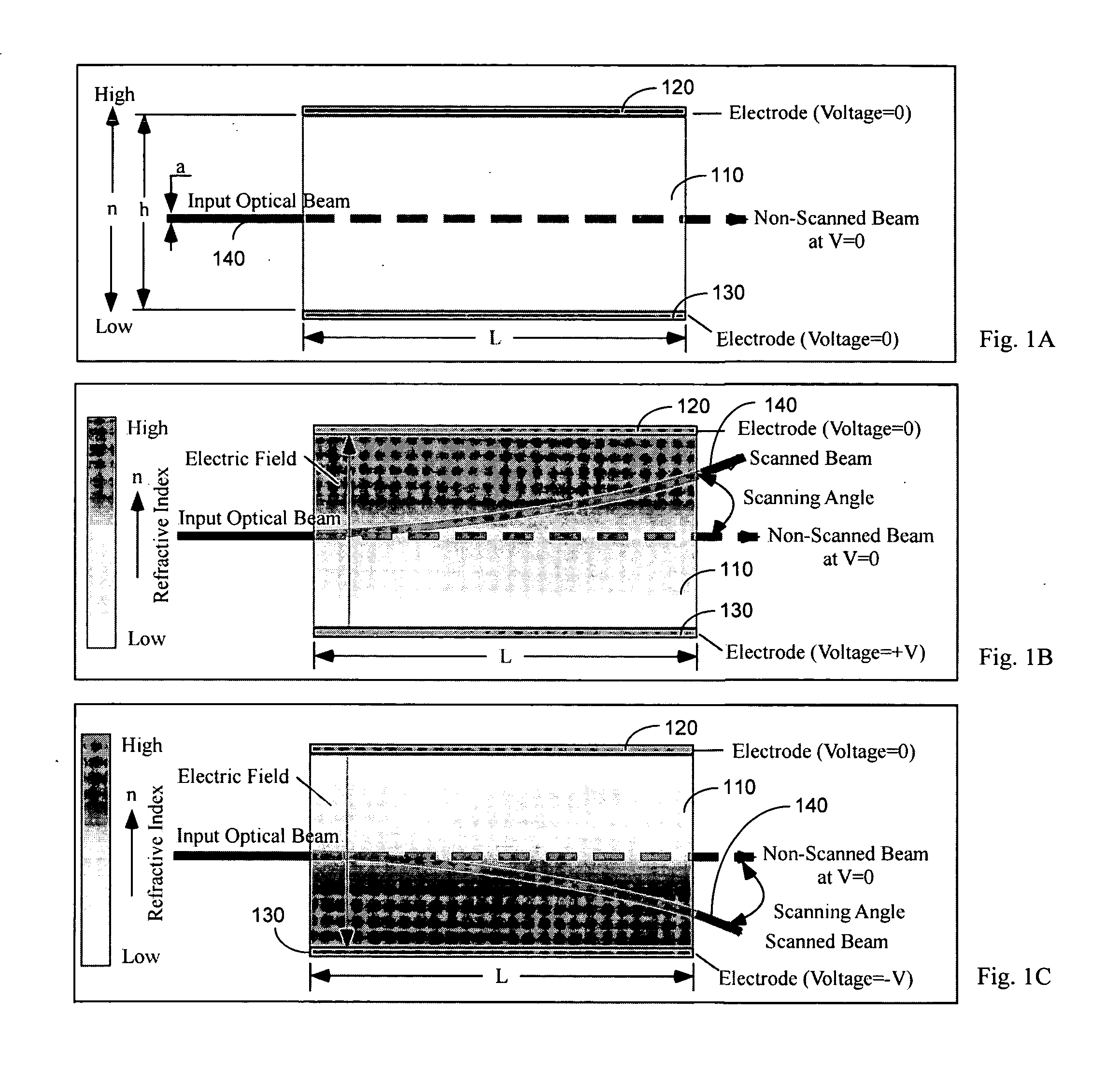
[0016]The graded electro-optic effect: the electro-optic coefficient varies gradually or step-by-step along the direction of applied electric field in an optical transparent crystal. As a result, the electro-optic index modulation changes gradually or step-by-step inside the crystal under applied electric field. Referring to FIGS. 1A to 1C for diagrams that illustrate one of the operation principles of the optical beam scanner based on graded electro-optic effect in a uniform optical transparent crystal. As shown in FIG. 1A, the optical beam scanner is formed with an optical transparent crystal 110 with graded electro-optic effect. (As an example, the crystal can be composed of materials such as KTa1-xNbxO3, K1-yLyTa1-xNbxO3, and Sr1-xBaxNb2O6). The crystal 110 is further coated with a top and bottom electrodes 120 and 130 respectively. The beam control is based on graded electro-optic effect in the electro-optic crystal 110. When an electric filed is applied to these crystals, it c...


PUM


Abstract

An electro-optical scanner includes an optical transparent crystal. The electro-optical scanner further includes an electrode for applying a voltage on the optical transparent crystal for applying an electric field therein for generating a graded electro-optic effect in the transparent crystal for deflecting an optical beam projected therethrough. The electro-optical scanner further includes a voltage controller for controlling the voltage applied to the optical transparent crystal for controlling the optical beam with a controlled deflecting angle projected through the optical transparent crystal.

Description

TECHNICAL FIELD[0001]This invention relates to the control of optical beam implemented typically in an optical scanner. More particularly, this invention relates to a solid-state optical scanner that is based on techniques of controlling and changing the electro-optic graded index.BACKGROUND ART[0002]Current beam steering systems are very complex, costly, and too large for most applications due to the required space for placement of the steering systems. Devices for controlling the direction of an optical beam have been limited in the past, and confined almost entirely to such methods as galvanic mirrors. The optical steering systems that implement these methods have been limited by various problems including scanning speed, driving power, and resolution of beam control. Furthermore, as such systems include more controlling and moving parts. More complex and costly fabrication and assembling processes are involved.[0003]Several device concepts for electro-optic deflectors have been ...

Claims


Application Information

Patent Timeline
IPC IPC(8): G02F1/29
CPCG02F1/0018G02F1/29G02F2001/291H01S3/0071G02F2203/24H01S3/005G02F2203/21G02F1/291
Inventor TANG, SUNING
Owner CRYSTAL RES
Why Eureka
Try Eureka