Light Emitting Diode Replacement Lamp

a technology replacement lamps, which is applied in the direction of lighting and heating apparatus, instruments, process and machine control, etc., can solve the problems of considerable heat, considerable waste, and substantial current consumption, and achieve the effect of increasing the temperature and reducing the resistance of light emitting diodes

Active Publication Date: 2008-06-05
LEDVANCE LLC
View PDF65 Cites 95 Cited by
  • Summary
  • Abstract
  • Description
  • Claims
  • Application Information

AI Technical Summary

Benefits of technology

[0024]Another embodiment involves a method for regulating current drive through at least one light emitting diode to compensate for temperature induced resistance changes in the light emitting diode. The method includes supplying a source voltage and using the source voltage to create a regulated current that is usable by the light emitting diode. The regulated current is applied to the light emitting diode to cause the regulated current to flow through the light emitting diode. A sense voltage is generated that is related to the regulated current and to a temperature at a position in a thermal pathway of heat emanating from the light emitting diode. The heat is produced by the light emitting diode responsive to the regulated current. The sense voltage is used as a feedback to modify the regulated current to be maintained within a non-destructive operating range of the light emitting diode when the regulated current would otherwise be outside of the non-destructive range due to a decreased resistance of the light emitting diode caused by an increased temperature of the light emitting diode.
[0025]Another embodiment involves a current regulator for regulating current through at least one light emitting diode to compensate for temperature induced resistance changes in the light emitting diode. The current regulator includes a source voltage that is connected to a voltage regulator. The voltage regulator is used for regulating the source voltage to create the regulated current and for connection to the light emitting diode to cause the current to flow through the light emitting diode. The current regulator also includes a sense voltage generator for generating a sense voltage that is related to the current and to a temperature at a position in a thermal pathway of heat emanating from the light emitting diode. The sense voltage is used as a feedback to modify the regulated current to be maintained within a non-destructive operating range of the light emitting diode when the regulated current would otherwise be outside of the non-destructive range due to a decreased resistance of the light emitting diode caused by an increased temperature of the light emitting diode.
[0026]Another embodiment involves a method for removing heat from at least one high power light emitting diode having an integral metal slug for transferring heat away from the light emitting diode. A printed circuit board is configured to electrically connect to the light emitting diode to generate light. At least one via is arranged in the printed circuit board in a location to contact the metal slug to transfer heat from the light emitting diode through the metal slug to the via. A heat sink is arranged in thermal communication with the via to receive heat from the via and to transfer the heat to the ambient environment.
[0027]Yet another embodiment involves an arrangement for removing heat from at least one high power light emitting diode having an integral metal slug for transferring heat away from the light emitting diode. A printed circuit board is electrically connected to cause the light emitting diode to generate light. At least one thermally conductive via in the printed circuit board is positioned in a location that is in thermal communication with the metal slug. A heat sink receives heat from the via and transfers the heat to the ambient environment.
[0028]Another embodiment involves a method for removing heat from at least one high power light emitting diode having an integral metal slug for transferring heat away from the light emitting diode. A printed circuit board is configured to electrically connect to the light emitting diode to generate light. The printed circuit board is arranged to define a hole adjacent to the metal slug. A heat sink is connected to the metal slug through the hole in the circuit board to transfer heat from the light emitting diode to the ambient environment.
[0029]Another embodiment involves an arrangement for removing heat from at least one high power light emitting diode having an integral metal slug for transferring heat away from the light emitting diode. The arrangement includes a printed circuit board that is electrically connected to the light emitting diode to generate light. The printed circuit board defines a hole adjacent to the metal slug. A heat sink is connected to the metal slug through the hole for transferring heat from the light emitting diode to the ambient environment.

Problems solved by technology

Because they use hot filaments, these products produce considerable heat, which is wasted, in addition to visible light that is desired.
These lights consume substantial current and dissipate considerable unwanted heat.
LEDs have an extremely long life compared to incandescent and halogen bulbs.
Moreover, unlike incandescent and halogen bulbs, LEDs are not shock-sensitive and can withstand large forces without failure, while the hot filament of an incandescent or halogen bulb is prone to rupture.
Too high an operating voltage causes premature failure, while too low an operating voltage or current reduces light output.
Furthermore, as the voltage to an incandescent and halogen light is reduced, its temperature drops, and so its internal resistance decreases, leading to higher current consumption, but without commensurate light output.
This is not easily accomplished using LEDs.
Halogen lights with their dichroic reflectors do this unintentionally, but ordinary incandescent lights employ external shades, not part of the light bulb, in a variety of artistic designs to make use of this otherwise misdirected light.
However, LEDs are subject to thermal damage or destruction at temperatures that are much lower than those tolerated by incandescent bulbs.
On the other hand, LEDs are subject to a thermal runaway condition in which excessive power causes the LED to heat and lower the LED internal resistance, which causes more current to flow and more heating to occur.
This thermal runaway can cause the operating life of the LED to be severely shortened or may lead to the rapid destruction of the LED.
These types of PCBs typically do not efficiently conduct the heat generated by the electrical components and LEDs away from the LEDs.
Metal core boards made with aluminum are more efficient at conducting heat away from the LEDs, however these boards are much more expensive and are limited to a single side to contain circuitry.
Typical metal core boards and fiberglass / copper PCBs used for high density LED light applications do not have sufficient heat conducting capacities to dissipate more than about 1 Watt away from LEDs.
Failure to control the heat at the LEDs can lead to the thermal runaway and subsequent damage of the LEDs.
Modulating the line voltage with a conventional dimming circuit does not produce the desired dimming effect on LED and CFL lighting because of the regulating circuits.
It is submitted that microprocessor based dimming controllers add unnecessary expense and complexity to LED lighting systems.
The microprocessors are also subject to heat from the LEDs which can affect the reliability of the circuits.

Method used


Image

  • Light Emitting Diode Replacement Lamp
  • Light Emitting Diode Replacement Lamp
  • Light Emitting Diode Replacement Lamp

Examples


Embodiment Construction

[0047]While this invention is susceptible to embodiment in many different forms, there are shown in the drawings, and will be described herein in detail, specific embodiments thereof with the understanding that the present disclosure is to be considered as an exemplification of the principles of the invention and is not to be limited to the specific embodiments described.

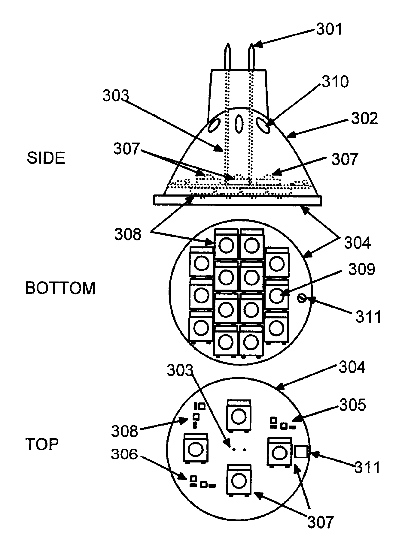
[0048]FIG. 1 illustrates an incandescent halogen type bulb commonly available. The features of this bulb have been derived from the operating characteristics implicit in the operation of these type illumination devices: they operate at high temperatures; they require an evacuated envelope separated from the hot filament; they emit large quantities of infrared radiation experienced by the user as heat; and they consume large quantities of electrical power. Nonetheless these devices are in common usage and fixtures and appliances have been constructed to accommodate the form, fit, and function of these bulbs. This par...


PUM


Abstract

Thermal management and control techniques for light emitting diode and other incandescent replacement light technologies using a current controller are disclosed.

Description

CROSS-REFERENCE TO RELATED APPLICATIONS[0001]The present application is a Continuation-in Part of copending application Ser. No. 10 / 820,930 filed Apr. 8, 2004; application Ser. No. 10 / 893,727 filed Jul. 16, 2004; and application Ser. No. 11 / 868,406 filed Oct. 5, 2007. application Ser. Nos. 10 / 893,727 and 11 / 848,406 claim priority from Provisional Application 60 / 517,130 filed Nov. 4, 2003 and application Ser. No. 10 / 820,930 claims priority from Provisional Application 60 / 502,495 filed Sep. 12, 2003. All of the aforementioned patent applications, from which this patent application claims priority, are incorporated herein by reference in their entire.BACKGROUND[0002]1. Field of the Invention[0003]The present invention relates to a light emitting diode (LED) illumination device and method and more specifically to a light emitting diode, integrated with electronic circuitry.[0004]2. Description of Related Art[0005]Currently lighting applications are dominated by incandescent lighting pro...

Claims


Application Information

Patent Timeline
Patent Type & Authority Applications(United States)
IPC IPC(8): F21V29/00H01J7/24H05B41/36H05B41/16H05B44/00
CPCF21Y2101/02H05B33/0803H05B33/0818H05B33/0821H05B33/0854F21V23/003Y02B20/383Y02B20/347F21K9/137H05B33/0884H01L2224/48091H01L2924/00014H01L2224/48137H01L2224/48464F21K9/233F21Y2115/10F21K9/238F21Y2105/10F21K9/23F21V23/005H01L2224/48227H01L2224/73265H05B45/14H05B45/18H05B45/38H05B45/3725Y02B20/30H05B45/40H05B45/10H05B45/56H05B45/3574
Inventor CATALANO, ANTHONYHARRISON, DANIELHALL, JOHN
Owner LEDVANCE LLC
Why Eureka
Try Eureka