Zero voltage switch method for fly-back converter

a converter and zero-voltage switch technology, applied in the direction of electric variable regulation, process and machine control, instruments, etc., can solve the problems of bad cross regulation, and switching noises that transmit back into power lines or radiate into space, so as to reduce the loss of switching and disturbance, the effect of low conduction and reducing the size of the converter

Inactive Publication Date: 2008-06-05
KUAN KAN SHENG
View PDF6 Cites 18 Cited by
  • Summary
  • Abstract
  • Description
  • Claims
  • Application Information

AI Technical Summary

Benefits of technology

[0019]The primary objective of the present invention is to provide a ZVS method, which is based on a negative conduction mode that allows and terminates the current flow in a reverse direction to reduce switching loss and disturbance in low conduction loss synchronous rectified converter systems and inverters, and to regulate a multi-output converter without compromising the efficiency.

Problems solved by technology

The advance of the high-frequency switching power supply technique reduces the size of the converter, but new issues arise in which the switching noises transmit back into power lines or radiate into space.
Another problem of the prior arts is bad cross regulation.
This is called bad cross regulation.
With a cascade converter, the same power is converted repeatedly, so the conversion loss is the sum, and the efficiency is reduced.
There are many methods on ZVS and post-regulation, but no one has taken care on both ZVS and cross regulation of a multi-output converter.

Method used


Image

  • Zero voltage switch method for fly-back converter
  • Zero voltage switch method for fly-back converter
  • Zero voltage switch method for fly-back converter

Examples


Embodiment Construction

[0060]The following description starts from the basic structure of the present invention, followed by its derivates and applications. The real application may use any composition of the basic invention or its derivative techniques, and it may repeatedly be used in different combinations.

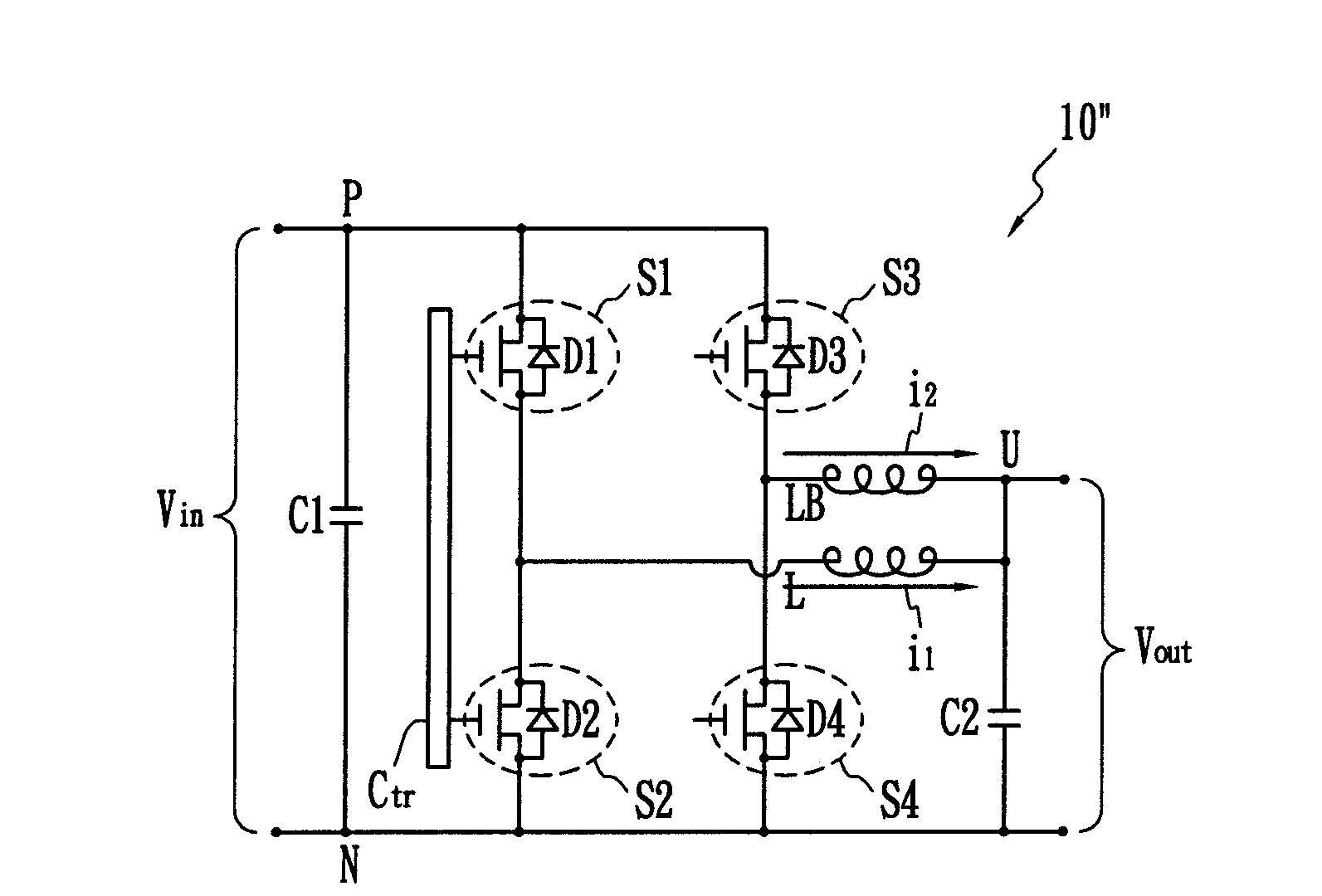
[0061]The key idea of the present invention works on synchronous converters, in which the synchronous switch is controlled beyond the range of prior art; that is, negative conduction mode.

[0062]Some terms used hereinafter are defined as follows. The term “switch module” means a MOSFET connected to a diode in parallel. The term “active” refers to the period in which the MOSFET of the switch module is turned on to be conductive, allowing a current to flow through. The term “passive” is defined as the period in which the switch module allows a current to flow through the diode of the switch module only in one direction. The term “open” or “opened,” means the switch module is non-conductive. When a curre...


PUM


Abstract

The present invention discloses a zero voltage switch (ZVS) method for the synchronous rectifiers and inverter. The ZVS method for synchronous rectifier, in which the rectifier diode is replaced by a bi-directional-current one directional-voltage blocking capability switch, by allowing and terminating current flow in a reverse direction, zero voltage turn-on is achieved on both inverter and rectifier switches. The ZVS method of the present invention comprises the steps of (a) increasing an inductor current to a current upper limit with a first switch module active; (b) decreasing the inductor current with the first switch module open and a second switch module passive; (c) decreasing the inductor current with a second switch module active; (d) turning the second switch module open when the inductor current turns negative; (e) increasing the inductor current from a current lower limit with the first switch module passive; and (f) increasing the inductor current with the first switch module active with zero voltage.

Description

[0001]This application is a continuation application of and claims priority to application Ser. No. 11 / 273,710, filed Nov. 14, 2005, and the disclosure of which is incorporated by reference.BACKGROUND OF THE INVENTION[0002]1. Field of the Invention[0003]The present invention relates to a zero voltage switch (ZVS) method for converters, particularly to a ZVS method based on a negative conduction mode that allows and terminates the current flow in a reverse direction, which is more suitable for switching synchronous rectifiers and inverters.[0004]2. Description of the Related Art[0005]The conversion of AC line voltage to low DC voltage is commonly used in electronic appliances. Sometimes it is made as a separate independent module known as an adapter, which is used in a notebook PC, an LCD monitor / TV, a charger, etc. Sometimes it is embedded within the appliances, known as an open frame, such as in a desktop PC, a TV, a medium-sized charger, etc. The same technique may also be used fo...

Claims


Application Information

Patent Timeline
Patent Type & Authority Applications(United States)
IPC IPC(8): H02M3/335
CPCH02M3/1588Y02B70/1475Y02B70/1466H02M3/33592Y02B70/10H02M1/0058
Inventor KUAN, KAN SHENG
Owner KUAN KAN SHENG
Why Eureka
Try Eureka