Optical pickup and optical disk apparatus

Inactive Publication Date: 2008-06-05
SONY CORP
View PDF8 Cites 2 Cited by
  • Summary
  • Abstract
  • Description
  • Claims
  • Application Information

AI Technical Summary

Benefits of technology

[0009]However, those non-cylindrical laser diodes are difficult to mount such that the optical axis of the laser diode is rotated in order to optimize the shape of a beam spot formed on a track. Further, since the rotated non-cylindrical laser diode is mounted, the height of the laser diode is increased, thus preventing miniaturization of an optical pickup including the laser diode.
[0011]According to an approach to preventing the increase in the width of the package 3, a relay mirror 4 can be used. The relay mirror 4 reflects a laser beam emitted from the laser diode 1 to the top emission prism 2 as shown in FIG. 10. Disadvantageously, the number of components constituting an optical pickup is increased. Unfortunately, an error in assembly of the optical pickup may be easily caused.
[0015]In accordance with this embodiment, the single prism allows for parallel shift of a laser beam and upward deflection thereof. Advantageously, when the light emitting device is rotated in order to optimize the shape of a laser beam spot on a track, the width of the optical pickup can be minimized.
[0017]In accordance with this embodiment, the single prism allows for parallel shift of a laser beam and upward deflection thereof. Advantageously, when the light emitting device is rotated in order to optimize the shape of a laser beam spot on a track, the width of the optical pickup can be minimized.
[0018]According to each of the embodiments of the present invention, when the light emitting device is rotated in order to optimize the shape of a laser beam spot oh a track, the width of the optical pickup can be minimized, since the single prism allows for parallel shift of a laser beam and upward deflection thereof. Advantageously, a small and simplified optical pickup capable of optimizing the shape of a laser beam spot on a track and an optical disk apparatus including the optical pickup can be realized.

Problems solved by technology

However, those non-cylindrical laser diodes are difficult to mount such that the optical axis of the laser diode is rotated in order to optimize the shape of a beam spot formed on a track.
Disadvantageously, the entire size of an optical pickup is increased.
Disadvantageously, the number of components constituting an optical pickup is increased.
Unfortunately, an error in assembly of the optical pickup may be easily caused.

Method used


Image

  • Optical pickup and optical disk apparatus
  • Optical pickup and optical disk apparatus
  • Optical pickup and optical disk apparatus

Examples


Embodiment Construction

[0030]Embodiments of the present invention will now be described with reference to the accompanying drawings.

(1) Structure of Optical Disk Apparatus

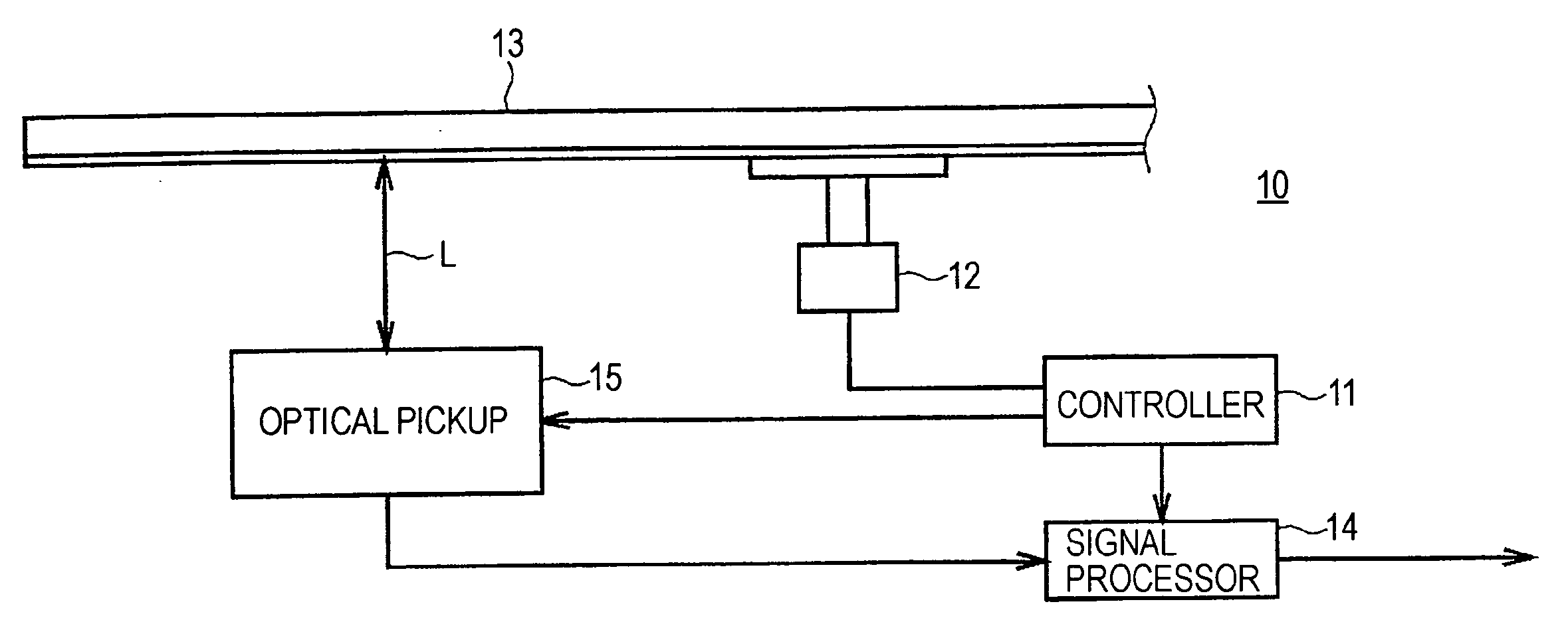
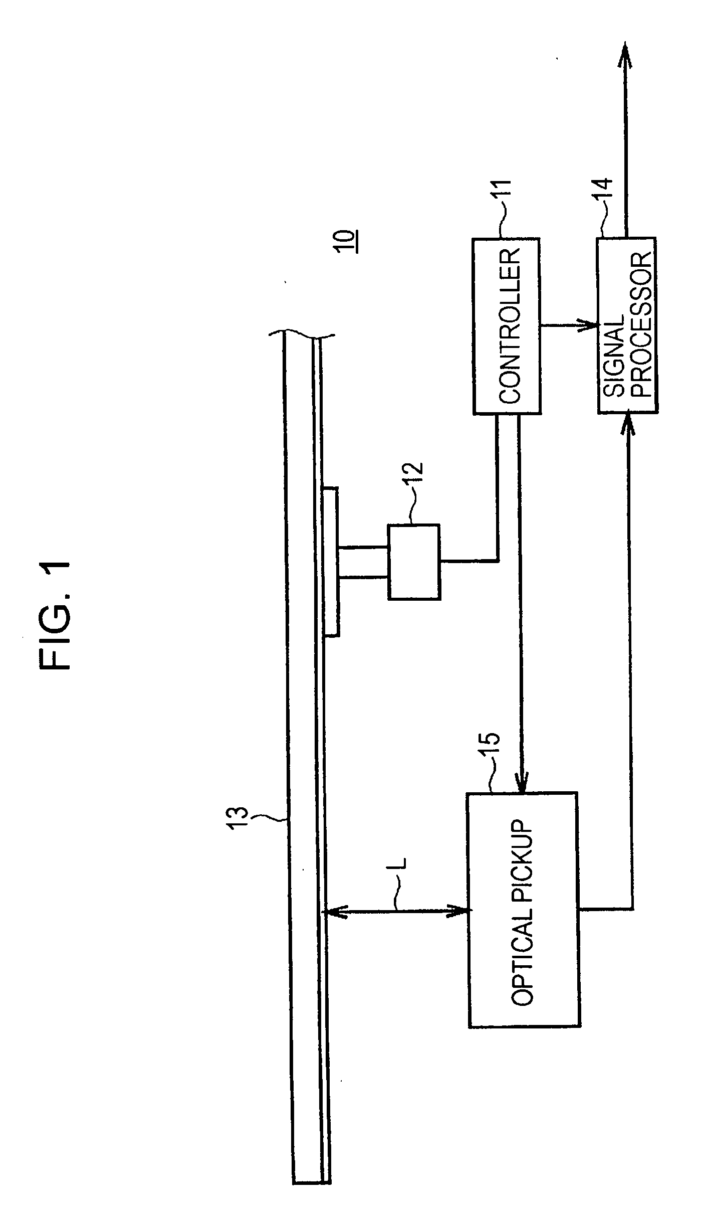
[0031]FIG. 1 shows an optical disk apparatus 10 according to an embodiment of the present invention. A controller 11 controls the entire optical disk apparatus 10. The controller 11 controls a motor 12 to rotate an optical disk 13 and also controls an optical pickup 15 to irradiate the optical disk 13 with a laser beam. The optical pickup 15 detects a laser beam reflected by the optical disk 13, generates a reproduction signal, and supplies the signal to a signal processor 14. The signal processor 14 performs predetermined signal processing on the reproduction signal and outputs the resultant signal to the outside.

(2) Structure of Optical Pickup

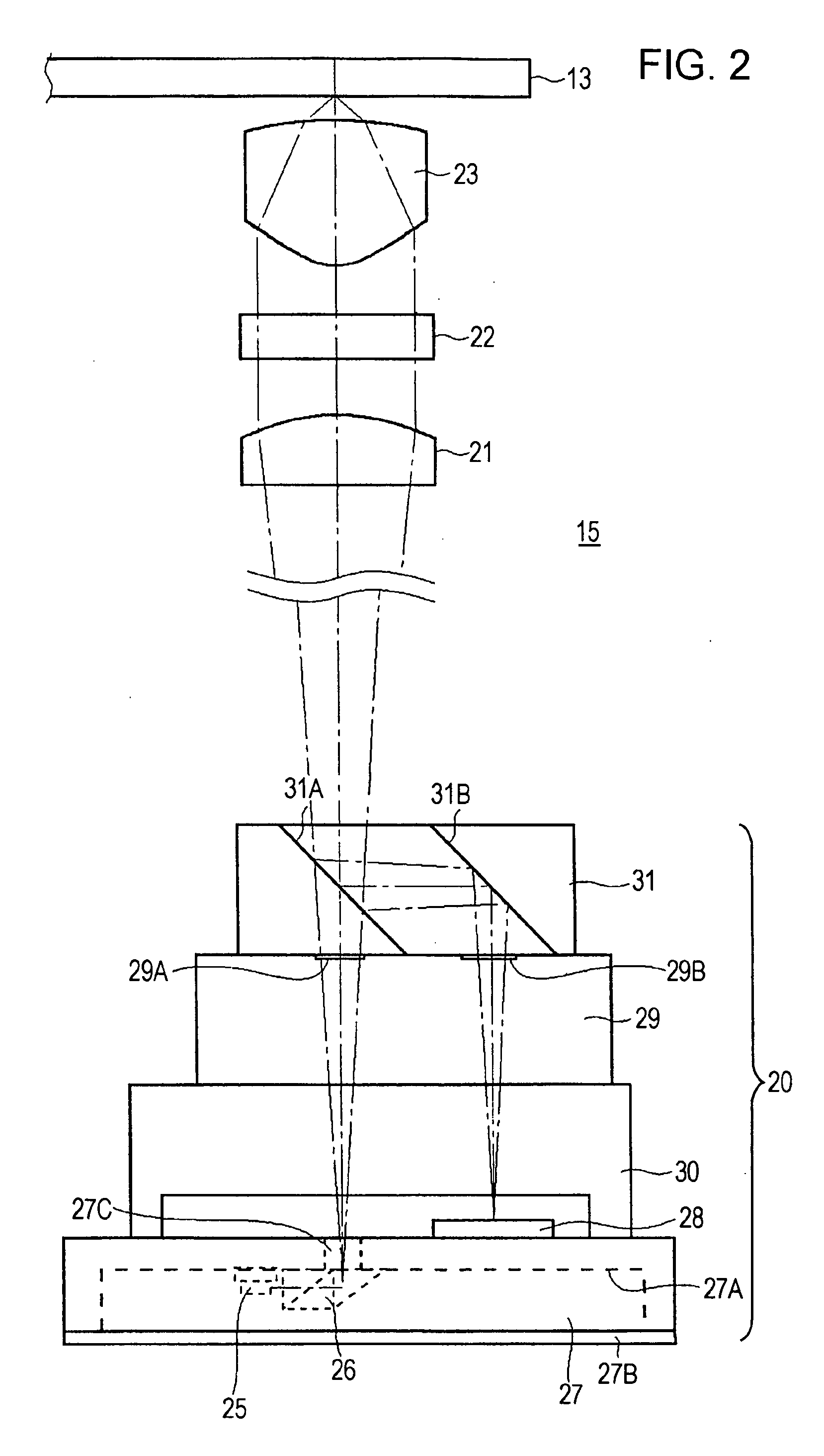
[0032]FIG. 2 shows the structure of the optical pickup 15 according to an embodiment of the present invention. The optical pickup 15 includes an optical assembly 20, a collimating lens 21, a quart...


PUM


Abstract

An optical pickup includes a light emitting device, a prism, and an objective lens. The light emitting device emits a laser beam. The prism has an entrance face and an exit face. In the prism, the laser beam emitted from the light emitting device is perpendicularly incident on the entrance face, is parallel-shifted, is perpendicularly reflected, and is emerged from the exit face. The objective lens focuses the laser beam emerged from the prism on a recording surface of an optical disk.

Description

CROSS REFERENCES TO RELATED APPLICATIONS[0001]The present invention contains subject matter related to Japanese Patent Application JP 2006-172988 filed in the Japanese Patent Office on Jun. 22, 2006, the entire contents of which are incorporated herein by reference.BACKGROUND OF THE INVENTION[0002]1. Field of the Invention[0003]The present invention relates to optical pickups for use in optical disk apparatuses.[0004]2. Description of the Related Art[0005]Laser diodes have been widely used as laser sources of optical pickups for used in optical disk apparatuses. The laser diodes have many advantages. For example, since the size of each laser diode is small and the power consumption thereof is low, the size of an optical pickup including the laser diode can be minimized.[0006]A laser beam emitted from a laser diode has an elliptical cross-sectional shape (far-field pattern). Consequently, a spot formed by focusing the laser beam through an objective lens is also elliptical. In an opt...

Claims


Application Information

Patent Timeline
IPC IPC(8): G11B7/00
CPCG11B7/1359G11B7/125
Inventor KOBAYASHI, TAKASHI
Owner SONY CORP
Why Eureka
Try Eureka