Method for detecting zero-field resonance

Active Publication Date: 2015-07-30
QUSPIN
View PDF0 Cites 24 Cited by
  • Summary
  • Abstract
  • Description
  • Claims
  • Application Information

AI Technical Summary

Benefits of technology

[0006]This invention relates to the use of a ZF-PRM in any magnetic field environment, including in unshielded magnetic field environments, using an apparatus and accompanying methods provided herein to actively null the background or ambient magnetic fields. The act of nulling a field, wherein the field is effectively equal to zero, can occur when the width of the measured resonance is minimized and height is maximized, and is therefore said to be optimized. This nulling may b

Problems solved by technology

Precisely zeroing the magnetic field is a complex and cumbersome task and often requires precise a priori knowledge of the ambient field.
Zeroing the field using only the magnetometer signal is extremely difficult and inefficient, especially when the field amplitude is much larger than the magnetic linewidth.
“Because the earth fie

Method used


Image

  • Method for detecting zero-field resonance
  • Method for detecting zero-field resonance
  • Method for detecting zero-field resonance

Examples


Example

Example 1

[0084]A ZF-PRM, simply referred to here as a magnetometer, was constructed in the following manner. The magnetometer housed a glass vapor cell in a shape approximating a cube having dimensions of about 4 mm)×4 mm×4 mm. The cell was vacuum processed and filled with an alkali vapor consisting of enriched rubidium-87 at a purity level exceeding 80% compared to other rubidium isotopes. Additionally, a buffer gas was added to the cell and the cell was sealed by melting the glass fill stem. The cell was mounted into a custom-built, non-metallic housing. A fiber coupled diode laser at about 795 nm was used to create a pump light beam. The diode laser was placed about 2 meters away from the magnetometer and the pump beam was delivered to the magnetometer with a polarization-maintaining, single-mode optical fiber. A lens in the magnetometer housing was used to collimate the pump beam from the optical fiber. Additional optical components such as polarizers, waveplates, and mirrors we...

Example

Example 2

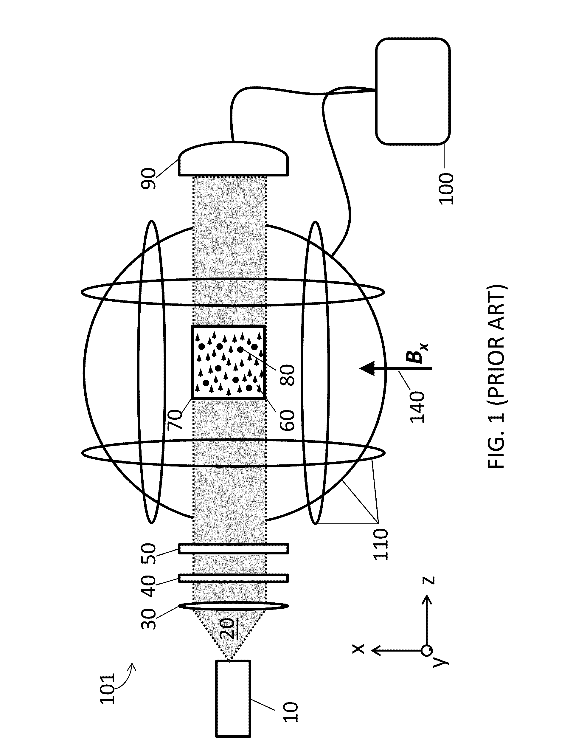
[0086]The magnetometer described above was placed in a non-shielded, open-air environment, randomly oriented with respect to the Earth's magnetic field. Using the iterative prior art method of stepping through the bias field, we characterized the time required to find the zero-field resonance of a ZF-PRM magnetometer in this un-shielded environment. The magnetometer was oriented so that Earth's field was not substantially along the direction of the pump beam. We turned on the pump beam and did not observe a ZF resonance due to the unknown field and direction. We started our search for the ZF resonance by setting the applied z-bias field to zero and stepping through values of x-bias fields and y-bias fields. After searching through values of x-bias fields and y-bias fields, we reset the x and y values and made a small change in the z-bias field. We then began our search anew by adjusting x-bias fields and y-bias fields for that particular z value. We iterated this process fo...

Example

Example 3

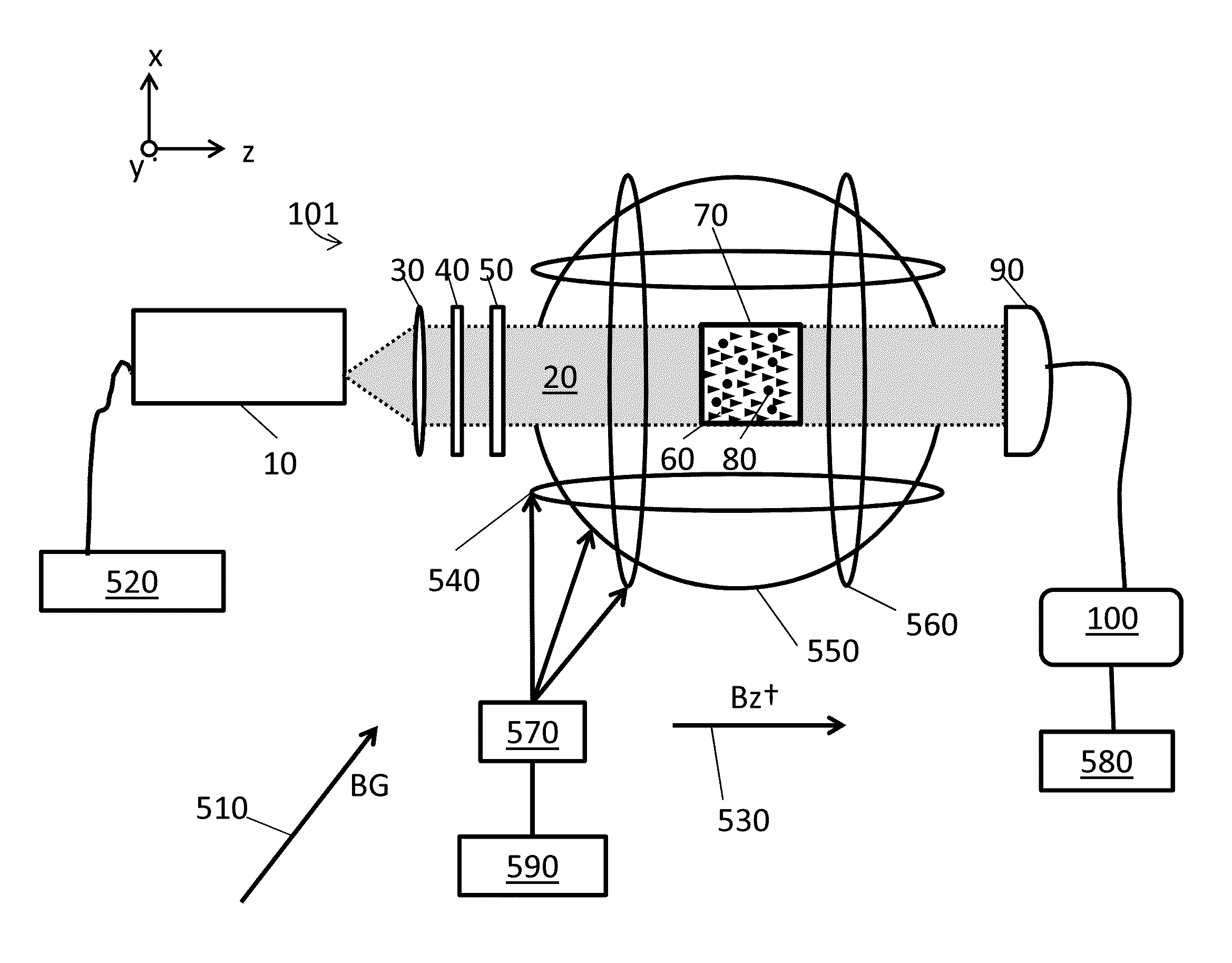
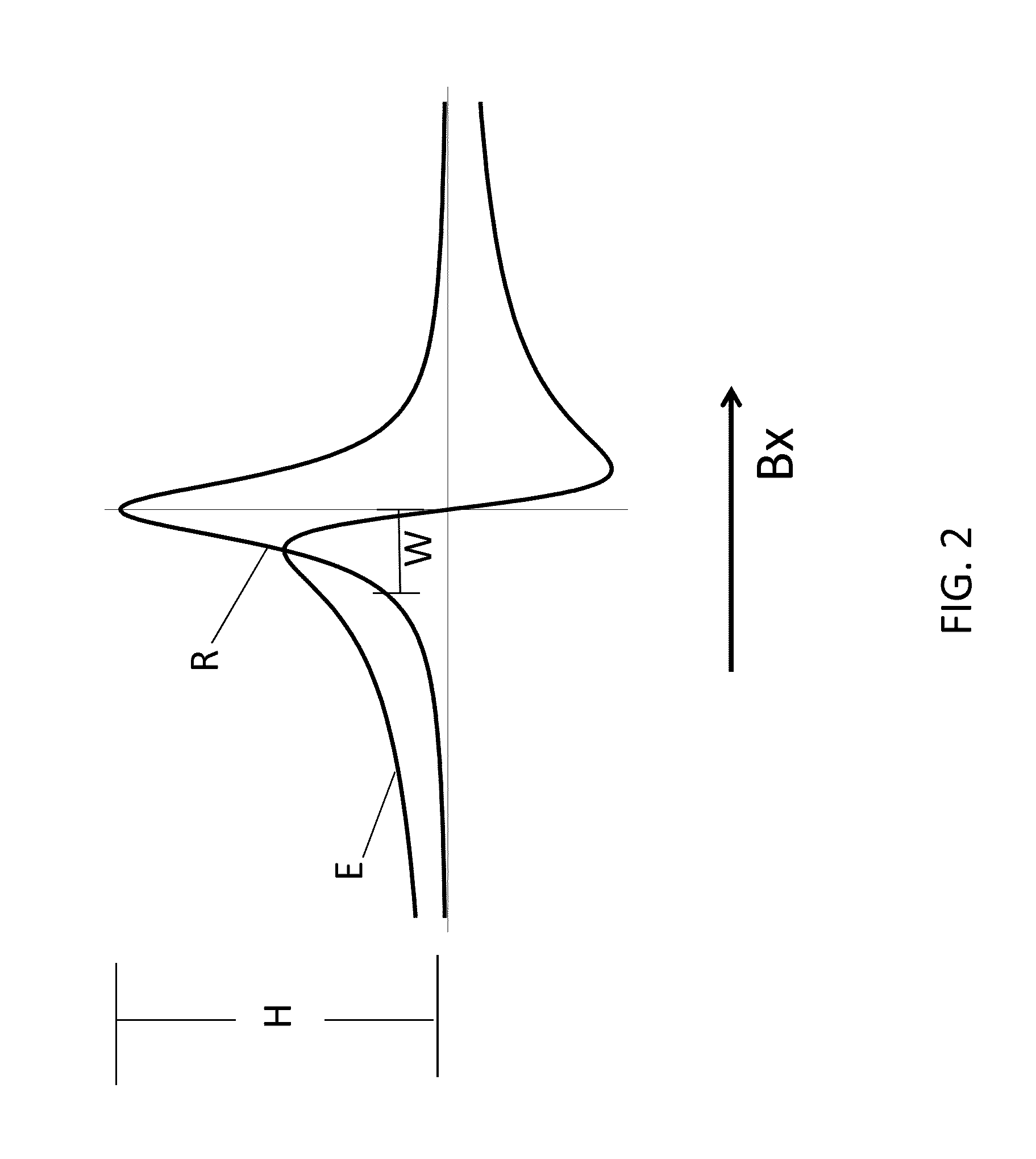
[0087]To test the efficiency and ease of use of the example magnetometer system and method of the present invention, the magnetometer, described above, was again located in an un-shielded, open air environment exposed to the Earth's magnetic field as in Example 2. As in Example 2, we oriented the magnetometer so that Earth's field was not substantially along the direction of the pump beam. We turned on the pump beam and did not observe a ZF resonance due to the unknown field and direction. Using the z-bias coils we applied a magnetic bias field, Bz†, in the direction of the pump beam which is along the z-axis. The applied field had a magnitude of about 100 μT which is about twice Earth's magnetic field, or in other words about twice the maximum expected field. Immediately after applying the bias field Bz†, a strong transmission signal was easily observed due to the induced broadening of the resonance and the increased strength of the resonance. By scanning the current in th...


PUM


Abstract

A zero-field paramagnetic resonance magnetometer (ZF-PRM) system and method for quickly and efficiently finding and optimizing the zero-field (ZF) resonance is described. In this system and method a magnetic coil is used to apply a magnetic bias field in the direction of the pump beam to artificially broaden the width and maximize the strength of the ZF resonance. By making the ZF resonance easy to detect, the ZF resonance may be found quickly found without the use of additional components and complex algorithms. Once the ZF resonance is found, a compensating magnetic field can be applied to null the magnetic field in the vicinity of the vapor cell in the ZF-PRM, thereby initializing it for operation.

Description

REFERENCE TO RELATED APPLICATIONS[0001]This application claims priority to U.S. Provisional Application No. 61 / 965,455 filed Jan. 30, 2014.FIELD OF INVENTION[0002]This disclosure relates to the field of paramagnetic resonance magnetometers and in particular a magnetometer and an accompanying method for detecting background magnetic fields. Further, the disclosure relates to a method for compensating for the background magnetic field and measuring a target magnetic field.BACKGROUND[0003]High sensitivity magnetometers, including paramagnetic resonance magnetometers (PRM) (Slocum & Reilly, 1963), have a wide range of applications including, but not limited to the following: fundamental research, detecting biomagnetic signals (such as those emanating from biological organisms, including the human body), geophysical exploration and prospecting, navigation and space applications, and military uses (such as ordinance and underground-underwater structure detection). Until recently, the most...

Claims


Application Information

Patent Timeline
IPC IPC(8): G01R33/26
CPCG01N24/006G01R33/26G01N24/10
Inventor SHAH, VISHALHUGHES, KENNETH JERAMIAH
Owner QUSPIN
Why Eureka
Try Eureka