Method and Device of Reconstructing an (N+1)-Dimensional Image Function from Radon Data

a radon data and function technology, applied in the field of methods and devices of reconstructing an n+1-dimensional image function from radon data, can solve the problems of inability to reconstruct images with fine details, long calculation time, and errors and artifacts that tend even to increase, so as to achieve the effect of greatly reducing the number of operations

Inactive Publication Date: 2008-06-05
HELMHOLTZ ZENT MUNCHEN DEUTES FORSCHUNGSZENT FUR GESUNDHEIT & UMWELT +1
View PDF6 Cites 31 Cited by
  • Summary
  • Abstract
  • Description
  • Claims
  • Application Information

AI Technical Summary

Benefits of technology

[0019]The term “projection direction” used herein generally refers to the linear course of an energy input through the ROI in the (n+1)-dimensional space. In the 2- or 3-dimensional case, the projection direction can be defined by angles relative to a coordinate system used. If fan or cone beams are considered, the term “main projection direction” indicates the orientation of the central beam component in the fan or cone beam.
[0020]The Radon data measured at the ROI comprise a set of projection functions which have been determined corresponding to a plurality of predetermined projection directions running through the ROI. The n-dimensional data are collected with a certain number, which might in theory be infinite large, of “projections”. These projections are characterized by integrating the interesting effect over one-dimensional lines. By measuring a sufficient number of these integrated “projections”, important features of the object can be reconstructed from the Radon data.
[0021]The values of the projection functions generally are determined by the interaction (in particular attenuation, e.g. by absorption, scattering or reflection) of an energy input beam travelling through the ROI along the respective projection direction. While the projection function is a one-dimensional function, the entirety of projection functions corresponding to all available projection directions spans a space (Radon space) of higher dimensions. Generally, for reconstructing the (n+1)-dimensional image function, Radon data with n-dimensions are required. However, the reconstruction with Radon data having less dimensions is also possible.
[0022]The term “energy input beam” used herein refers to all types of a physical quantity, which travels along a straight line (or an essentially straight line) through the ROI while the energy carried is changed due to an interaction with the ROI. In particular, the term “energy input beam” covers electromagnetic radiation, particle radiation, sound waves or electrical current.
[0023]The term “Radon data” used herein refers not only to the data obtained by the above projections through the ROI, but also to data obtained by measuring an energy output obtained by reflection within the object investigated. These Radon data (or: Radon-like data) are obtained e.g. with the investigation of objects by the use of ultrasound waves. It is an essential advantage of the invention that the reconstruction of the image function can be implemented for Radon-like data.
[0024]According to a preferred embodiment of the invention, the image function ƒ has two, three or four dimensions with n being selected from 1, 2 or 3. The reconstruction of a 2-dimensional image function ƒ has the particular advantage in that the multiplication of the polynomials with values of the projection functions can be done with low computational power. The 2-dimensional image function represents e.g. an image of a disc section in an object under investigation. The reconstruction of a 3-dimensional image function has an advantage in that the calculation for reconstructing the image function can be obtained by a simple adaptation of the 2-dimensional case. The invention-based calculation for the 2D and the 3D case are based on mathematical operations which can be implemented in a very simple way, and with the possibility of precalculating a lot of values and store them within a computer or another data carrier, like e.g. a memory chip or chips. This means the number of operations will be greatly reduced as matrix elements (see equation 2.3 in section 3) can be precalculated.

Problems solved by technology

For an optimization of the reconstructed picture, this iteration is repeated many times. The essential disadvantage of the iterative reconstruction is that the above iteration leads to extremely long calculation times.
A general disadvantage of using the Fourier-slice theorem lies in the fact that an interpolation step in the reconstruction results in errors and artifacts which have a tendency even to increase with increasing space frequency.
The capability of reconstructing images with fine details is limited.
However, the application of these detectors is limited in terms of dose burden, costs and data processing time.
Another problem is related to the discretization of the Radon data from which the image data have to be reconstructed.
This drawback can in general not be overcome by filtered back-projection algorithms.
It could be avoided by using the above mentioned iterative reconstruction but these are so computational expensive that they are not widely used in practical computed tomography.
This leads to further uncertainties and unsharpness.
These developments are suffering from two further major problems.
First of all, the amount of data is very large, the reconstruction time for such an amount of data is too long or the computers needed to handle such data are too expensive.
The second problem is scatter radiation.
Scatter radiation becomes a bigger problem for larger radiated areas of the object.
Conventional scatter reduction methods like grids do not have enough effect and the signal-to-noise ratios are anyhow already very small, which means that a further reduction of signal as resulting from inserting a grid would produce more artifacts and worse images.
Additionally, assuming an oscillation of the grid relative to the detector to avoid grid lines, the rotation of the grid with the detector is very difficult in consideration of the rotation time of 0.5 s or less.
The above disadvantages are associated not only with the conventional CT imaging, but also with all available reconstruction methods related to Radon data.
As an example, a practical reconstruction technique for neutron transmission imaging is not available at present.

Method used


Image

  • Method and Device of Reconstructing an (N+1)-Dimensional Image Function from Radon Data
  • Method and Device of Reconstructing an (N+1)-Dimensional Image Function from Radon Data
  • Method and Device of Reconstructing an (N+1)-Dimensional Image Function from Radon Data

Examples


Embodiment Construction

[0083]The invention is described in the following text with reference to the application in computer tomography (sections 1., 2.1). It is emphasized that the invention can be implemented in an analogous way with the other applications mentioned above (examples in section 2.2). Furthermore, the following description of the preferred embodiments mainly refers to the data collection and the data processing. Details of the CT devices used for implementing the invention are not described as far as they are known from conventional CT devices.

[0084]The basic principles of reconstructing an image function representing an ROI are described in the following text with reference to FIGS. 1 and 2. The imaging method of the invention as well as details of imaging devices used according to the invention will be described with reference to FIGS. 3 to 14.

1. Basic Principles of Reconstruction and Imaging

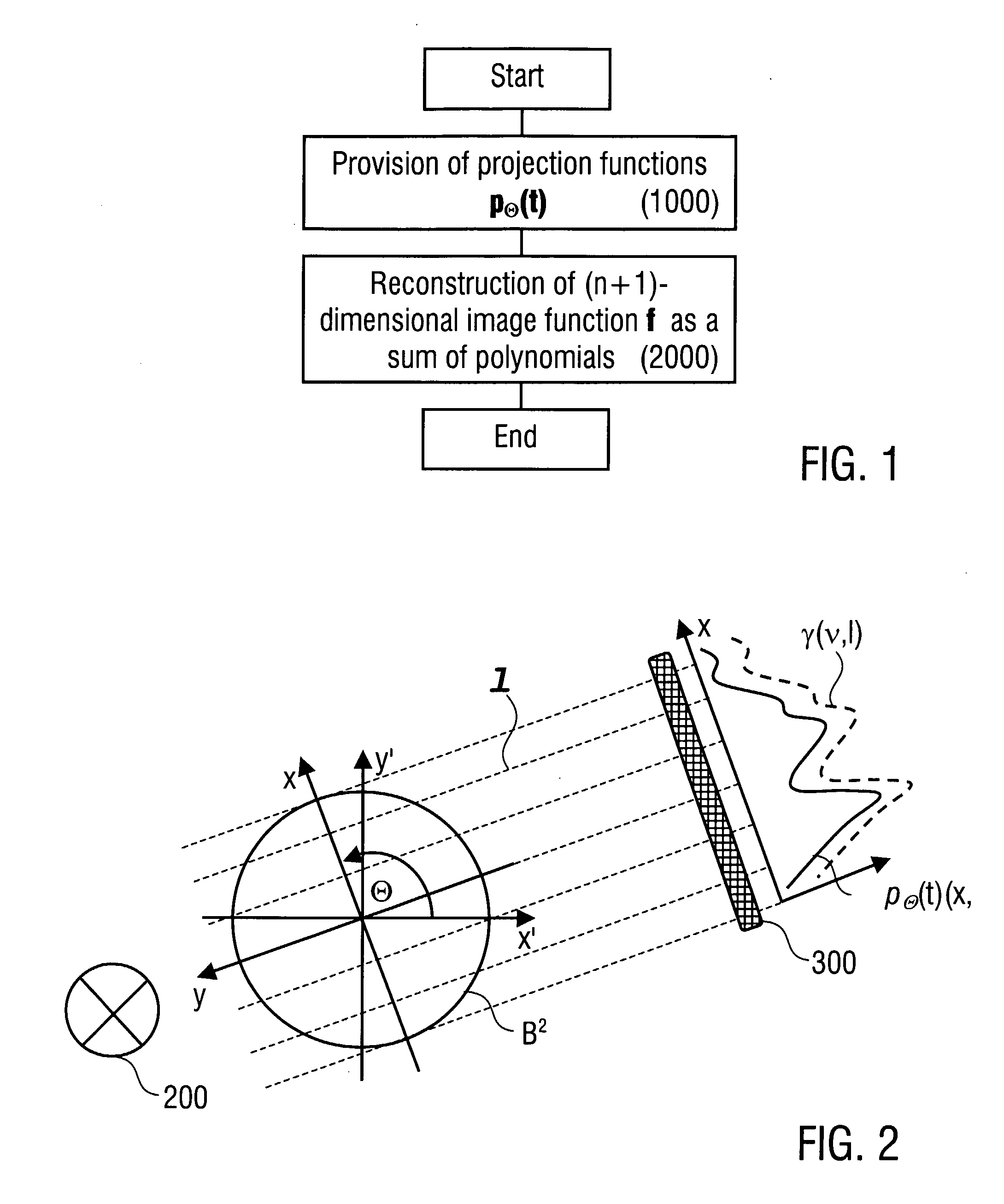
[0085](1.1) According to FIG. 1, the basic steps of a reconstruction method according to the inven...


PUM


Abstract

A method of reconstructing an (n+1)-dimensional image function ƒ representing a region of investigation comprises determining the image function ƒ from n-dimensional or less dimensional Radon data comprising a plurality of projection functions pθ(t) measured corresponding to a plurality of predetermined projection directions (Θ), wherein the image function ƒ is determined as a sum of polynomials multiplied with values of the projection functions pθ(t). Imaging methods, imaging devices, and computer tomography devices using this reconstruction method are described.

Description

CROSS-REFERENCE TO RELATED APPLICATIONS[0001]This application claims the benefit of U.S. Provisional Application 60 / 640,426, filed Dec. 30, 2004, and European Patent Application No. 04031043.5, filed Dec. 30, 2004.ACKNOWLEDGEMENT OF GOVERNMENT SUPPORT[0002]This invention was made with Government support under Grant No. DMS-02011669 awarded by the National Science Foundation, U.S.A. The Government of the United States of America has certain rights in the invention.TECHNICAL FIELD[0003]The present invention relates to a method of reconstructing an (n+1)-dimensional image function from n-dimensional or less dimensional Radon data comprising a plurality of projection functions measured corresponding to a plurality of predetermined projection directions. Furthermore, the present invention relates to a method and a device for imaging a region of investigation on the basis of the above reconstructing method.TECHNICAL BACKGROUND[0004]The non-destructive investigation of samples is an import...

Claims


Application Information

Patent Timeline
Patent Type & Authority Applications(United States)
IPC IPC(8): G06K9/00G06K9/36
CPCA61B6/032A61B6/06G06T2211/416G06T11/006A61B6/027A61B6/482G06T11/00
Inventor XU, YUANTISCHENKO, OLEGHOESCHEN, CHRISTOPH
Owner HELMHOLTZ ZENT MUNCHEN DEUTES FORSCHUNGSZENT FUR GESUNDHEIT & UMWELT
Why Eureka
Try Eureka