Blood Pump With An Ultrasonic Transducer

an ultrasonic transducer and blood pump technology, applied in the direction of heart stimulators, prostheses, therapy, etc., can solve the problems of increasing the risk of thrombogenesis or cloning, the described ultrasonic sensor and the blood pump are separate components, and the patient is bedridden and restricted to the hospital environmen

Inactive Publication Date: 2008-06-05
THORATEC CORPORTION
View PDF9 Cites 41 Cited by
  • Summary
  • Abstract
  • Description
  • Claims
  • Application Information

AI Technical Summary

Benefits of technology

[0009]Preferably the blood pump is a rotary blood pump and includes a shaft-less rotary impeller.

Problems solved by technology

The first disadvantage is that the arrangement requires the blood pump and ultrasonic sensor to be extracorporeal relative to the patient, which generally means the patient is bed ridden and restricted to a hospital environment.
The second disadvantage is that the described ultrasonic sensor and blood pump are separate components and are not part of an integrated system.
In addition, the arrangement described has a relatively large surface area of blood contacting regions which may increase the risk of thrombogenesis or cloning.
The third problem is that the described system does not include an automatic control system using the measurements from the ultrasonic transducer to allow a pump controller to automatically adjust the pumping speed set-point of the blood pump without the doctor or clinician manually adjusting the speed, therefore the described system relies entirely on the doctor or clinician detecting a problem and taking immediate action to remedy said problem.

Method used


Image

  • Blood Pump With An Ultrasonic Transducer
  • Blood Pump With An Ultrasonic Transducer
  • Blood Pump With An Ultrasonic Transducer

Examples


Embodiment Construction

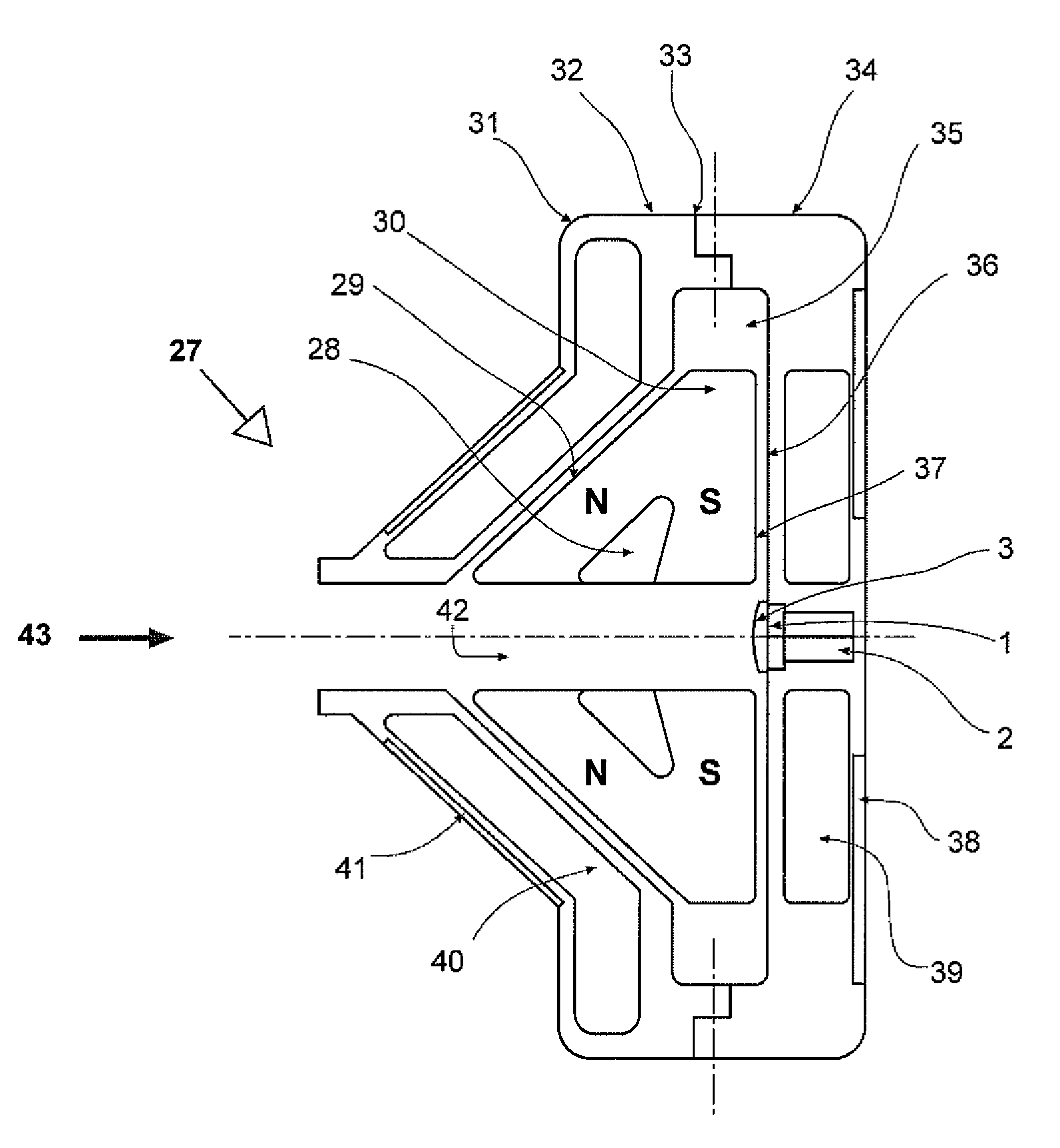
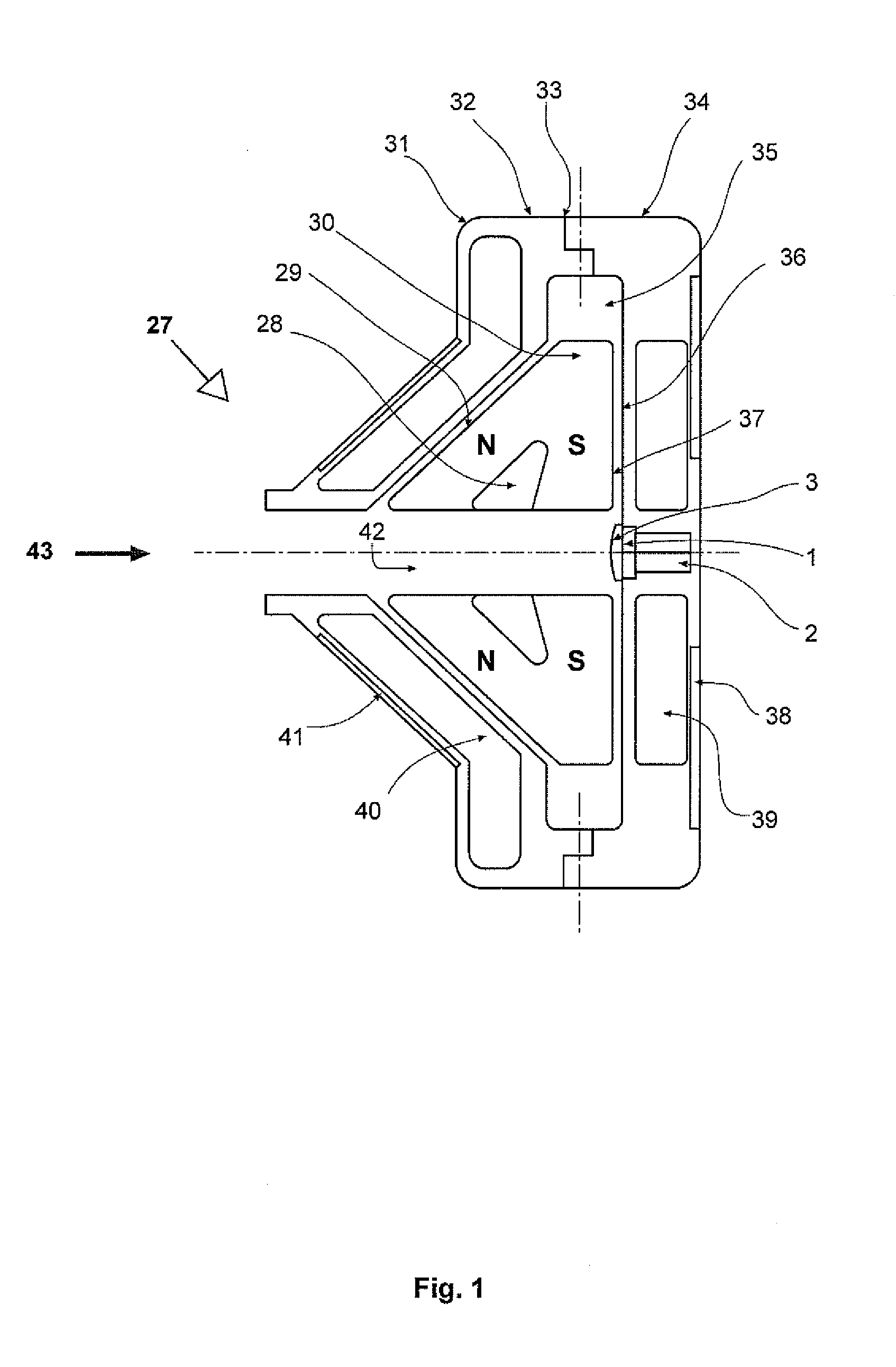
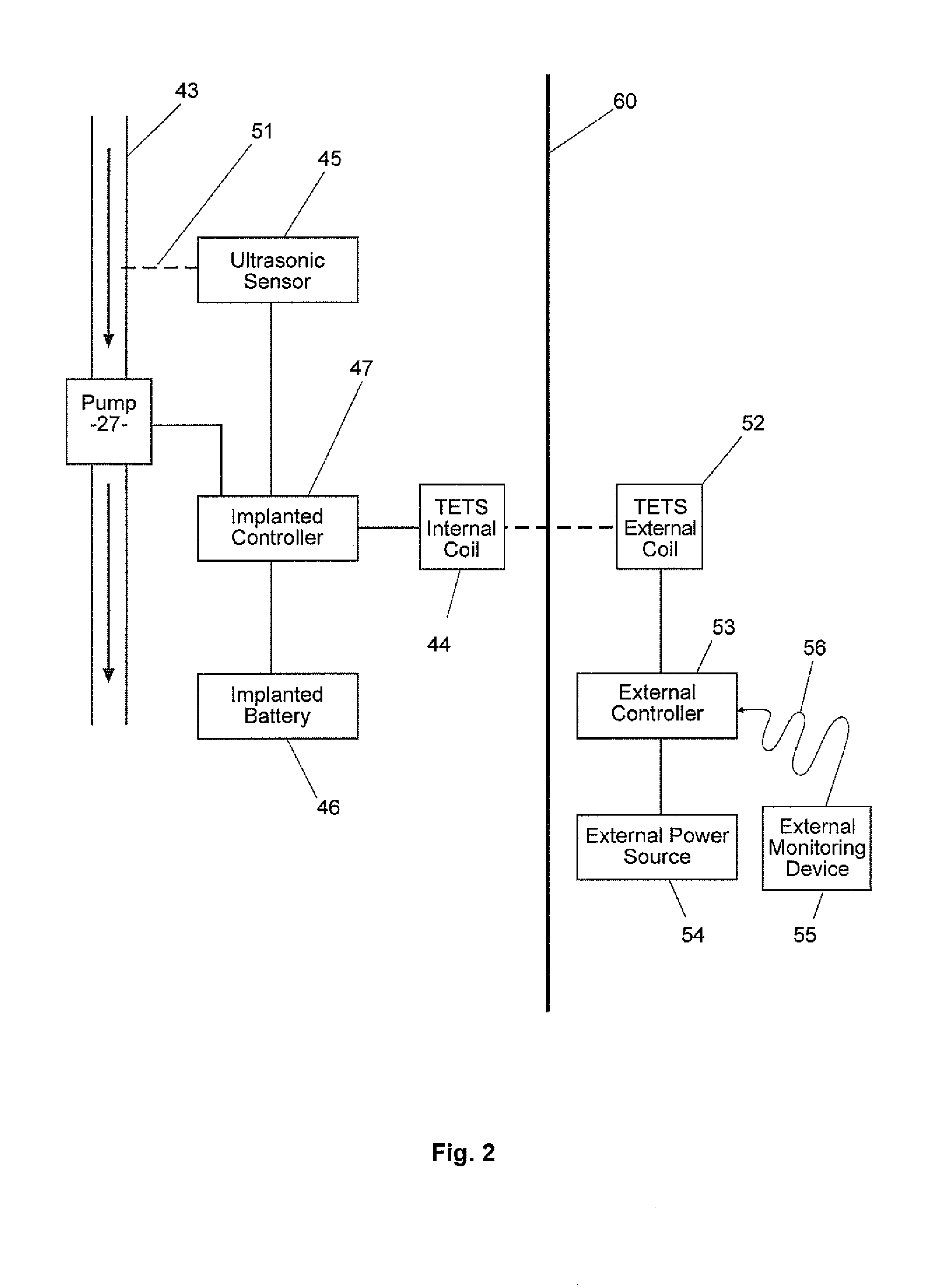
[0022]A first preferred embodiment of the present invention is depicted in FIGS. 1 & 2. In this first preferred embodiment, a blood pump 27 includes an impeller 30 mounted within a cavity 37 within a housing 32.

[0023]The most preferred blood pump for use with this first preferred embodiment is

similar to the blood pump described within U.S. Pat. No. 6,227,797 (Watterson et al). When in use, impeller 30 is magnetically urged to rotate by upper and lower stator coil assemblies 40&39 acting on permanent rare earth magnets 28 embedded within each blade of the impeller 30.

[0024]When in operation, impeller 30 is hydrodynamically suspended by thrust forces generated by tapered edges of the blades forming a “restriction area” as the blades rotate. The “restriction area” forms in a region of relatively high pressure in gaps 29&36 and this pressure forces impeller 30 away from housing 32 at an angle normal relative to the angle of the inner housing surface.

[0025]Furthermore, the preferred impe...


PUM


Abstract

A blood pump including a ultrasonic sensor mounted in or on a blood contacting surface of said blood pump. The ultrasonic sensor measures blood velocity and reports information to a blood pump controller and wherein the ultrasonic sensor is directed to measure blood velocity in an inflow cannula connected to the blood pump.

Description

TECHNICAL FIELD[0001]The present invention relates to an implantable blood pump with an ultrasonic transducer to detect and measure blood flow, and to enable ultrasound imaging.BACKGROUND OF THE INVENTION[0002]In the past, blood pumps have been used successfully to treat patients with late stage congestive heart disease or failure. Commonly, pulsatile blood pumps or continuous flow rotary blood pumps have been connected in parallel to a patient's heart to supplement or assist their heart in pumping blood through the patient's circulatory system. These types of blood pump are been commonly called left ventricular assist devices (LVADs) because they are generally connected between the left ventricle of the patients heart and the aorta to offload the heart.[0003]A preferred example of an implantable rotary blood pump is described in U.S. Pat. No. 6,227,797 (Watterson et al). This pump is a continuous flow blood pump which includes a hydrodynamically suspended impeller that rotates to i...

Claims


Application Information

Patent Timeline
Patent Type & Authority Applications(United States)
IPC IPC(8): A61M1/10
CPCA61M1/101A61M1/122A61M2205/3523A61M1/3663A61M2205/32A61M2205/3334A61M2205/8243A61M60/562A61M60/422A61M60/148A61M60/419A61M60/221A61M60/816A61M60/178A61M60/538A61M60/523A61M60/515A61M60/873A61M60/876
Inventor CROSBY, PETER ANDREWSUTTON, COLIN NEVILLEAYRE, PETER JOSEPH
Owner THORATEC CORPORTION
Why Eureka
Try Eureka