Quartz Sensor and Sensing Device

a technology of sensing device and quartz resonator, which is applied in the field of quartz sensor and sensing device, to achieve the effects of improving measurement sensitivity, high accuracy, and reducing the thickness of quartz resonator

Inactive Publication Date: 2008-06-12
NIHON DEMPA KOGYO CO LTD
View PDF28 Cites 19 Cited by
  • Summary
  • Abstract
  • Description
  • Claims
  • Application Information

AI Technical Summary

Benefits of technology

[0021]According to the present invention, in a quartz sensor using a Langevin type quartz resonator in which an adsorbing layer for adsorbing the object to be measured in the sample solution is formed on the one surface side, an opposing surface portion larger than the excitation electrode of the quartz resonator is provided, and measurement is conducted in a state that the sample solution is filled between this opposing surface portion and the excitation electrode. Accordingly, the liquid surface of the sample solution above the excitation electrode is in contact with the opposing surface portion, which results in no generation of surface tension. Accordingly, since no stress caused by the surface tension of the sample solution a

Problems solved by technology

When a quartz resonator is composed using this thin layered quartz piece, however, the quartz resonator easily receives the influence of surface tension of the sample solution to be measured, and there is a possibility of not causing oscillation owing to the surface tension or not

Method used


Image

  • Quartz Sensor and Sensing Device
  • Quartz Sensor and Sensing Device
  • Quartz Sensor and Sensing Device

Examples


first embodiment

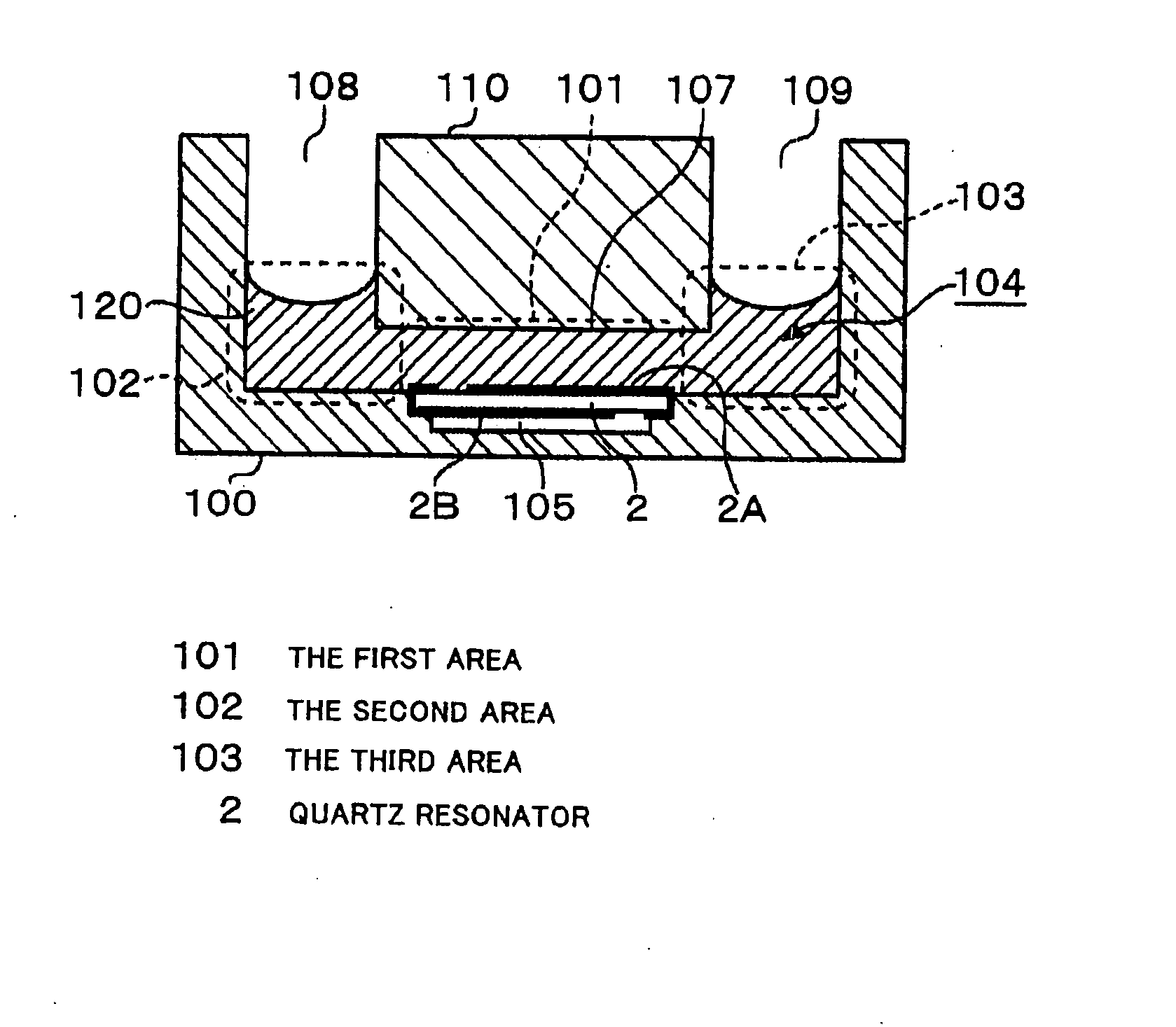
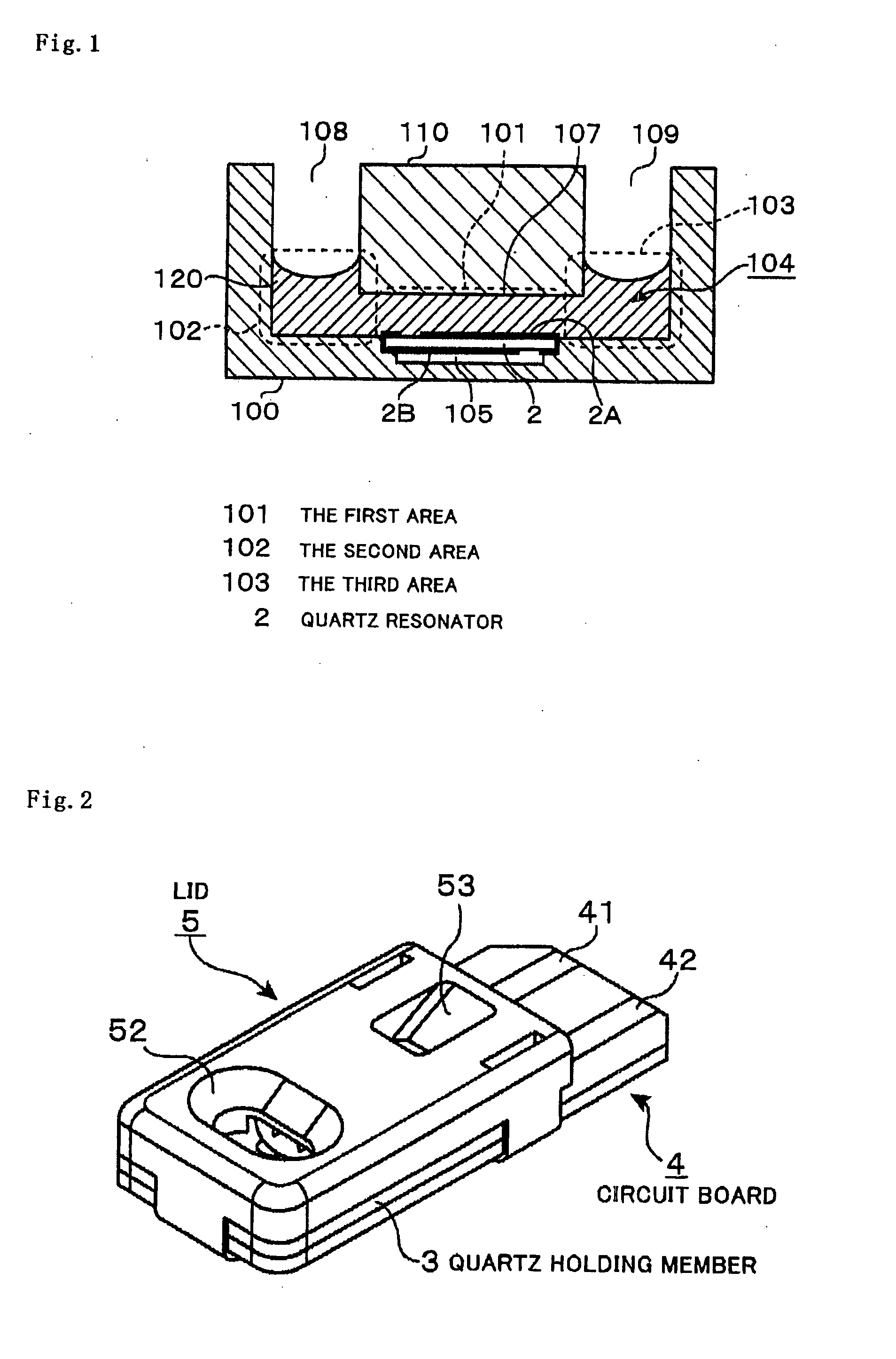
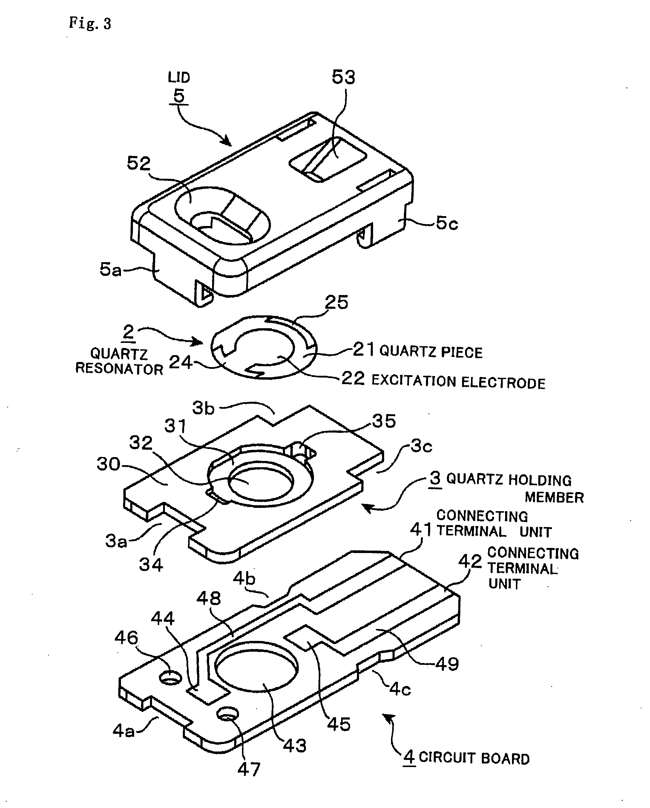
[0039]The first embodiment of the quartz sensor relating to the present invention will be explained using FIG. 2 to FIG. 5. FIG. 2 is a perspective view showing an example of the quartz sensor relating to the present invention. The quartz sensor is structured by placing one upon another composed of the respective parts of a circuit board 4, a quartz holding member 3, a quartz resonator 2 and a lid 5 in this order from the bottom. FIG. 3 is a exploded perspective view showing the upper surface sides of the respective parts of the quartz sensor.

[0040]The quartz resonator 2 includes a quartz piece 21, excitation electrodes 22 and 23, and derivation electrodes 24 and 25. The quartz piece 21 has an equivalent thickness of 1 μm to 300 μm, preferably 185 μm, and is formed in a plate in which a portion of the periphery is cut off straight. On one surface side and the other surface side of the quartz piece 21, one foil-shaped excitation electrode 22 and the other foil-shaped excitation elect...


PUM


Abstract

An object of the present invention is to provide a Langevin type quartz sensor which is high in measurement sensitivity, suppresses the influence of the surface tension of a sample solution during measurement, and enables an installed quartz resonator to stably oscillate. As a specific means to solve the problem, a quartz sensor including a housing area forming portion surrounding the upper space on one face side of the quartz resonator for forming a housing area of the sample solution; an opposing surface portion opposing to one surface side of the quartz resonator via the housing area and being larger than the area coming in contact with the sample solution in the quartz resonator; and a pouring opening formed in the outside area of the opposing surface portion and at a position higher than said opposing surface potion for pouring the sample solution into the housing area is composed and measurement is conducted in a standstill state where the sample solution is filled in the lower side of the opposing surface portion. Since stress due to the surface tension of the sample solution does not act in this state, the quartz resonator can oscillate with reliability. Therefore, the quartz sensor of the present invention can reduced the thickness of the quartz resonator, which realizes highly sensitive and highly accurate measurement.

Description

TECHNICAL FIELD[0001]The present inventor relates to a quartz sensor utilizing a Langevin type quartz resonator which is composed such that one surface of a quartz piece comes in contact with a measurement medium and the other surface faces an airtight space to sense an object to be detected by detecting variation in frequency, and to a sensing device using the quartz sensor.BACKGROUND ART[0002]A measuring method that uses a sensing device equipped with a quartz sensor using a quartz resonator for sensing a substance in minute quantities such as an environmental pollutant e.g. dioxin or the like, or a disease marker for the hepatitis C virus, a C-reactive protein (CRP), or the like has been widely known.[0003]To be more specific, the measurement method is conducted in such a manner that an adsorbing layer is formed in advance on an excitation electrode on one surface side of the quartz resonator, and the presence / absence of the object to be measured or the concentration thereof in a...

Claims


Application Information

Patent Timeline
IPC IPC(8): G01N5/02G01N29/036H01L41/053H01L41/18
CPCG01N29/022G01N2291/0256G01N29/222G01N29/036
Inventor WAKAMATSU, SHUNICHIKOYAMA, MITSUAKISHIOBARA, TSUYOSHI
Owner NIHON DEMPA KOGYO CO LTD
Why Eureka
Try Eureka