Tufting machine for producing athletic turf having a graphic design

a tufting machine and graphic design technology, applied in the field of tufting machines, can solve the problems of not being able to produce high-detailed color images, conventional tufting machines that employ backing feed mechanisms are not optimum for tufting multicolored designs, and tufting needles may fail to insert yarn tufts at the precise level, so as to increase production efficiency

Active Publication Date: 2008-06-12
SIGNATURE BANK OF GEORGIA +1
View PDF12 Cites 25 Cited by
  • Summary
  • Abstract
  • Description
  • Claims
  • Application Information

AI Technical Summary

Benefits of technology

[0008]It is an object of the present invention to provide an apparatus that employs individual needle control capability ing tufting a multicolored yarn pattern into a statically held backing fabric. In one aspect of the invention, the apparatus features a support frame to which the ends of sheet of backing material are clamped so that the backing is held in plane under uniform tension while being worked upon by a tufting head that moves about the backing. By holding the backing static, rather than feeding it through the machine during tufting, the present tufting machine exercises greater control over individual tuft position accuracy, as the backing is prevented from skewing like it could if conveyed by a feed mechanism of some sort. Furthermore, eliminating the aspect of advancing the backing material from the tufting process allows separate pieces of backing, which are to be adjacently laid upon and adhered to a separate base material, to be tufted with precise symmetry and continuity of their respective rows of yarn tufts.
[0010]It is another object of the invention to provide a tufting head configured to efficiently construct precise linear tuft rows comprised of different colors of yarn. In one aspect of the invention, the tufting head is formed by two distinct and independently movable carriages which are not mechanically linked and are disposed on opposite sides of the backing sheet, yet which interact to produce cut pile tufts of the type ordinarily found in artificial athletic turf. To accommodate a tufting head of such construction, the tufting frame to which it is mounted features two horizontal and X-oriented beams that respectively span above and below the horizontally suspended backing. The “tufting head” itself is formed by: (a) a needle carriage which is movably mounted to the aforementioned upper beam and includes multiple needles which are each selectively reciprocated in order to insert different colored yarn into the backing fabric; and (b) a looper carriage which is movably mounted to the lower beam and that includes a conventional yarn looper for catching yarn on a needle's downward stroke and then holding it in place as the needle returns upward to, thereby, form a yarn loop, and that further includes a cutting knife for severing the just formed loop to render a cut pile. By virtue of the tufting frame's ability to advance in Y-directions along the support frame and the ability of the tufting head carriages to travel in X-directions along the tufting frame, the tufting needles are able to assume precise lateral and longitudinal tufting positions for inserting yarn in accordance with a detailed graphic pattern stored in the computer.
[0012]This aspect of the machine is particularly important due to the how the tufting head traverses the backing fabric, during the tufting process, in order to tuft yarn row-by-row. To with, in creating each row of tufts, the needle carriage generally advances in one lateral direction while its individually controlled needles selectively insert their yarns. If the row being created is to contain different yarns (ex: red and blue), occasionally, a trailing needle threaded with one color of yarn will need to remain idle while advancing past a segment of its designated tufting positions while a leading needle carrying a different colored yarn is commanded to insert a continuous span of its yarn along a segment of its designated tufting positions within that row. Then, when the leading needle finishes its segment, the needle carriage will reverse course in order to reposition the trailing needle to initiate tufting along its previously neglected stretch of tufting positions. By minimizing needle gauge, the cumulative distance of reverse travel by the needle carriage is effectively reduced, and the amount of time consumed in tufting a complete multicolored row is reduced accordingly.
[0013]It is another object of the invention to provide a tufting head configured to minimize the quantity of parts that are subject to wear and, eventually, fail from usage. Employing a single looper and knife to engage the yarn of multiple needles makes the present apparatus considerably easier to maintain than most conventional tufting machines that have a separate looper and cutter stationed to correspond with each of multiple tufting needles. One obvious reason for that is the fact that, with the present machine, only one looper or cutter ever needs replacing. Furthermore, if the looper ever fails during use, the needle carriage can be repositioned and the machine set to resume executing the exact same tufting sequence beginning at the precise position that the needle carriage was at when the looper failed. However, when a looper on a prior art tufting machines fails, the tuft row left partially uncompleted due to the failure might have to be completed by manual tufting in order to avoid the yarn overlapping that might result from re-running its tufting head over backing positions at which yarn loops were successfully formed, before the prior art machine was stopped, by other loopers that continued functioning properly.
[0015]It is yet another object of the present invention to increase production efficiency by allowing multiple tufting heads to work on different sections of a backing fabric simultaneously. For example, separate tufting heads (i.e., separate needle and looper carriage pairings) can be mounted along the same tufting frame, with the heads operating on different width sections of the backing. Alternatively or additionally, multiple tufting frames can be mounted along the support frame of the tufting machine, with the tufting head(s) attached to each tufting frame operating on a separate length section of the backing.

Problems solved by technology

However, while broadloom tufting machines that employ single axis needle bar movement may be preferable for high output production of tufted products of uniform tuft placement and yarn color, they are not ideal for tufting multicolored designs.
However, conventional tufting machines that employ backing feed mechanisms are not optimum for producing highly detailed color images, such as some artistic logo-bearing sections of artificial athletic turf, even if their tufting heads are laterally shiftable.
Whenever that motion relationship is altered, as may occur unintentionally for a variety of reasons, the tufting needles may fail to insert yarn tufts at the precise positions necessary to produce the desired image effect.
For example, if the backing feed mechanism experiences any lag or surge in its operation, that will likely create inconsistency in the longitudinal spacing between adjacent rows of tufts which, in turn, could distort the overall graphic image being tufted.
However, using a conventional tufting machine with a backing feed mechanism to tuft the various adjacent sections of backing separately can be problematic, not only because the machine may experience operating irregularities in the cooperative motions of its tufting head and backing feed mechanism, but also due to inherent characteristics of the backing material itself.

Method used


Image

  • Tufting machine for producing athletic turf having a graphic design
  • Tufting machine for producing athletic turf having a graphic design
  • Tufting machine for producing athletic turf having a graphic design

Examples


Embodiment Construction

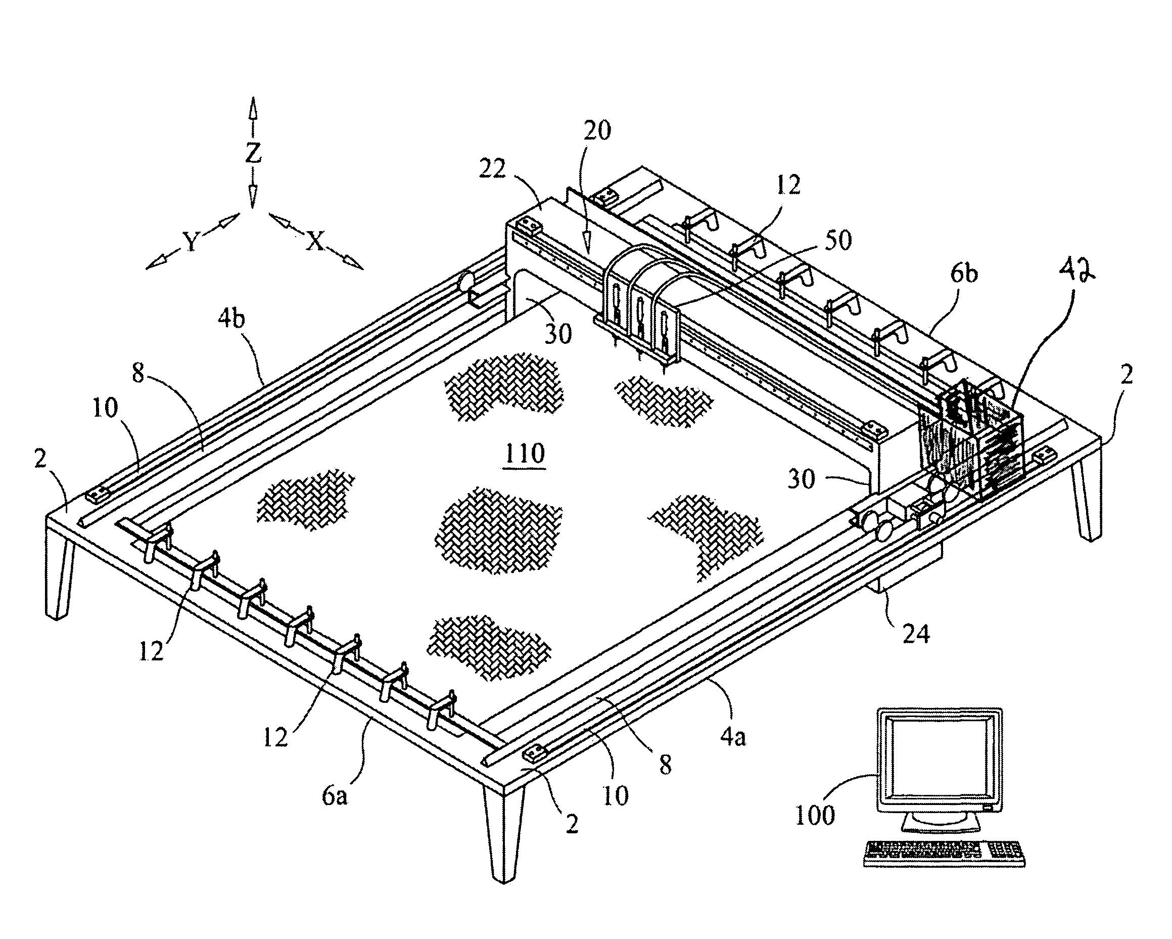
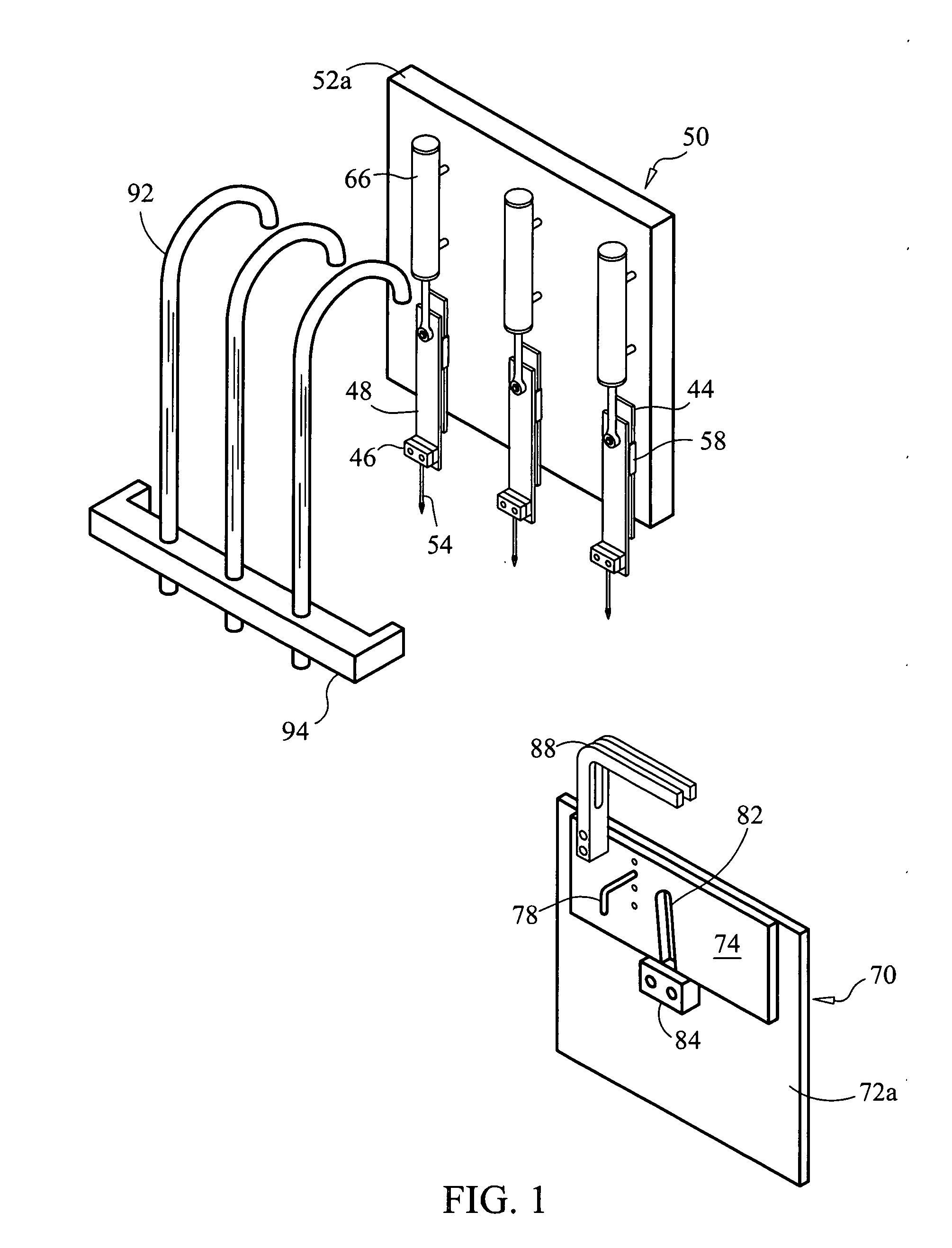
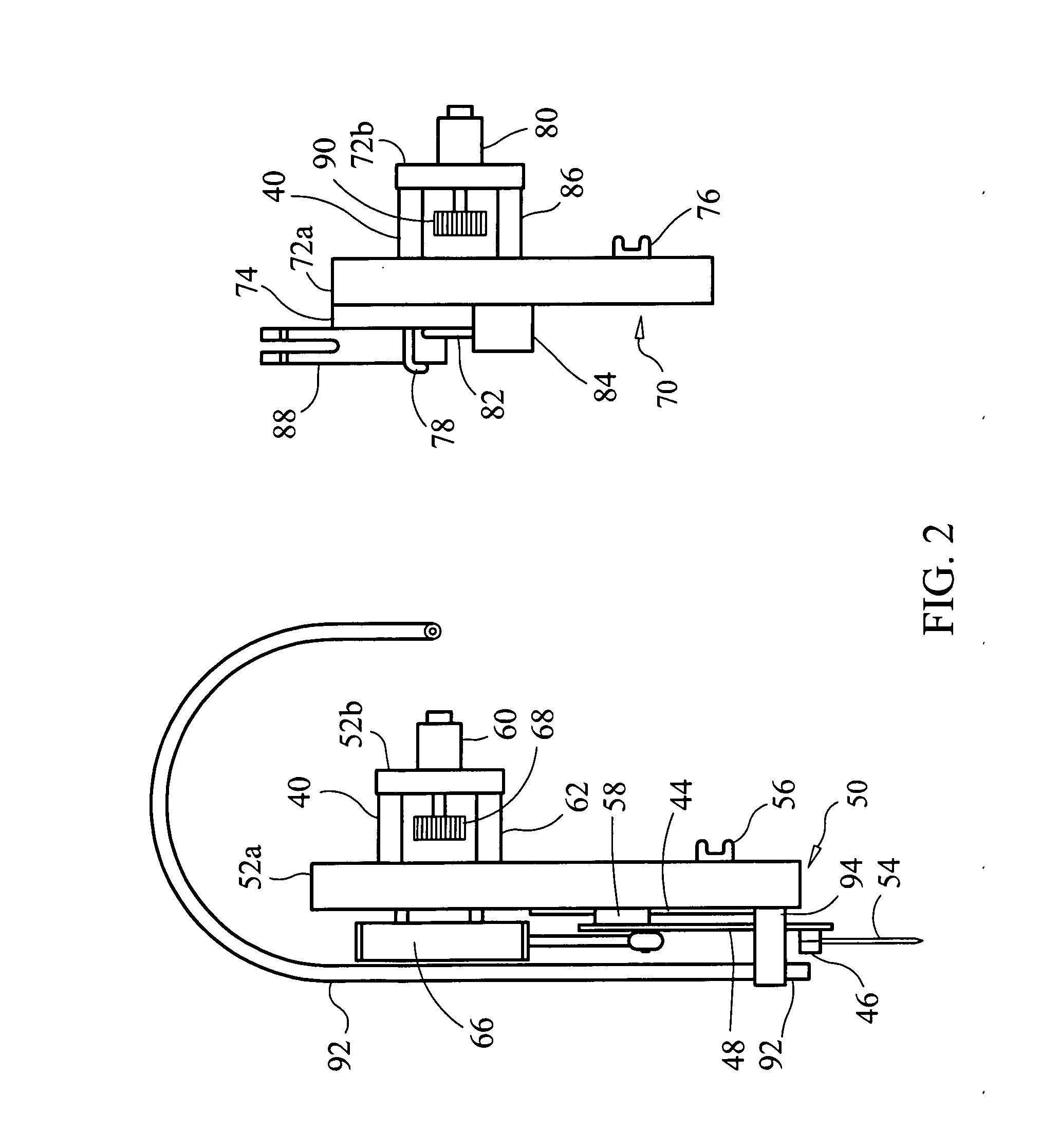
[0023]It should be understood that the present disclosure has particular applicability to machines used for manufacturing graphically designed portions of artificial athletic turf and other cut pile articles, but it can be applicable to tufting machines generally. This disclosure, as embodied in FIGS. 3-5, relates to a tufting apparatus 1 which can be viewed as generally comprising three basic elements: an apparatus support frame 2, a tufting frame 20 and a tufting head which, itself, comprises a needle carriage 50 and looper carriage 70. Additionally, a computer 100 is used to control all of the selective motions imparted by various drive components of the apparatus 1 throughout its operation. It is particularly important that the tufting frame 20 be movable along a Y-axis relative to the support frame 2, that the tufting head be movable along an X-axis relative to the tufting frame 20 and that, as will be explained, yarn-receiving looper carriage components 70 of the tufting head ...


PUM


Abstract

A tufting machine capable of producing individual articles of athletic turf bearing precise graphic patterns is disclosed. The machine includes a support frame to which a backing material is statically held, a tufting frame that spans above and below the backing and is computer-controlled to travel along the support frame, a yarn-inserting needle carriage disposed above the backing along the tufting frame and a yarn-catching looper carriage disposed below the backing along the tufting frame. The carriages are computer-controlled to asynchronously shift relative to each other as may be necessary for their individual yarn-inserting components and yarn-catching components to cooperate

Description

BACKGROUND[0001]The present invention generally relates to tufting machines, and it is specifically directed to a tufting machine that has a tufting head comprised of distinct yarn-inserting and yarn-catching / cutting elements that are independently movable relative to each other in order to facilitate the production of artificial athletic turf bearing multi-colored graphic designs.[0002]Many of the aspects and features of machines for manufacturing tufted products have evolved considerably over the years. Conventional broadloom tufting machines have been designed to enable the manufacture of carpet and artificial athletic turf in high volume. Such high output tufting machines typically feature a backing feed mechanism comprising an arrangement of feed and take-up rollers that feed an elongate sheet of backing fabric past a tufting head. The tufting head portion of the machine generally features one or more elongate needle bars having hundreds of aligned tufting needles which are dis...

Claims


Application Information

Patent Timeline
Patent Type & Authority Applications(United States)
IPC IPC(8): D05B19/00D05B23/00
CPCD05C15/34
Inventor BEARDEN, JOHN H.
Owner SIGNATURE BANK OF GEORGIA
Why Eureka
Try Eureka