Audio filter using a diode connected mosfet

a diode connected, filter technology, applied in pulse manipulation, frequency selective two-port network, pulse technique, etc., can solve the problem of only present audio signal, and achieve the effect of attenuating any audio signal and high value resistan

Inactive Publication Date: 2008-06-12
SEMICON COMPONENTS IND LLC
View PDF5 Cites 5 Cited by
  • Summary
  • Abstract
  • Description
  • Claims
  • Application Information

AI Technical Summary

Benefits of technology

[0009]A diode connected transistor, in one embodiment a diode connected P-type CMOS, provides a high value resistance that is placed in series with a conductor carrying a digital signal to a control input of a digital gate. A capacitor is formed from that control input to a low impedance signal return. The values of equivalent...

Problems solved by technology

However, the audio signal is only ...

Method used


Image

  • Audio filter using a diode connected mosfet
  • Audio filter using a diode connected mosfet

Examples


Embodiment Construction

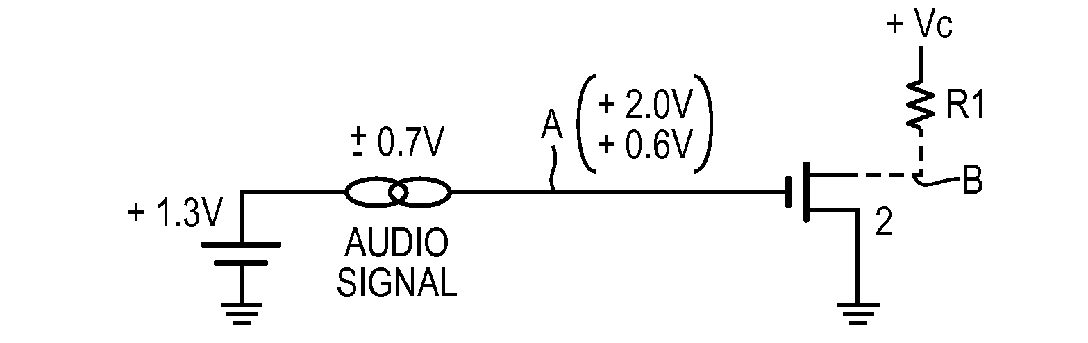
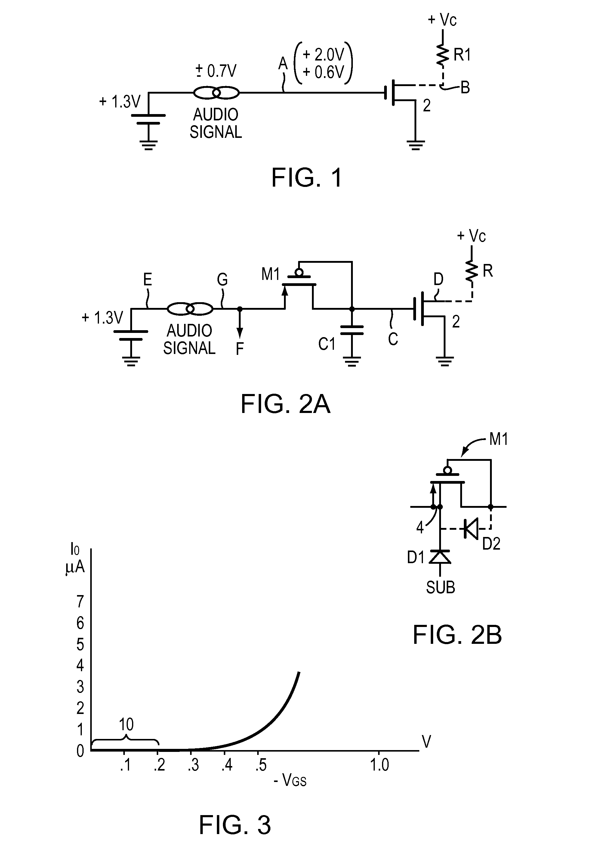
[0018]FIG. 2A adds a series P-type CMOS, M1, and a bypass capacitor C1 to the circuit of FIG. 1. The source of M1 is at a typical DC +1.3V level and a possible interfering audio signal is shown. The design provides that M1 and C1 attenuates the audio signal so that the N-type CMOS 2 does not turn off during the negative peak of the audio signal, as it did in FIG. 1 discussed above.

[0019]Referring to FIG. 2A, if the gate input C is at 0V, M1 is connected as a diode, as point E rises to the +1.3 volt level, current will flow through the diode (M1) and charge C1. As C1 charges, the voltage across M1 will decrease until it is in the sub-threshold range. At this point, as shown in FIG. 3, some microAmp current will continue to charge C1 until the voltage across M1 is in the 0.1-0.2 V range. At a Vgs of 0.2V, the equivalent resistance of M1 is a very high value (in the gigaOhms), and point C might remain at about 1.0 to 1.1V. The CMOS 2 will be on, assuming its threshold is about 0.7V, an...


PUM


Abstract

A diode connected P-type CMOS transistor is operated in the sub-threshold area and, with a bypass capacitor, operates as a low pass audio filter. The equivalent resistance of the CMOS transistor in the sub-threshold range is very high—in the gigaOhm range. With this size resistor, a capacitor in the 1-25 pF range may be used to provide filtering capabilities with break points in the 1-10 Hz frequency range. Such a filter provides an effective low pass filter that attenuates audio frequency signals. The 1-25 pF capacitors use little chip area making the arrangement practical for integrating on an IC with the audio signals. In one embodiment, a digital signal and the audio signals share one pin, where the audio signal appears only when the digital signal is high. In this case, the audio signal filtered out from the digital high signal. The filtered digital signal drives digital circuitry while the audio signal is directed to other audio circuitry.

Description

BACKGROUND OF THE INVENTION[0001]1. Field of the Invention[0002]The present invention relates to low pass electronic filters using high value resistors and capacitors suitable for fabricating on a silicon IC (Integrated Circuit), and more particularly to a low pass filter that attenuates the audio frequency range, but is efficient in its use of chip area.[0003]2. Background Information[0004]Audio frequency electronic components typically require high value capacitors that are unsuited for placing in silicon ICs since the chip area needed is large. Large resistors may be more easily obtained in silicon, but large value capacitors are very inefficient with respect to chip area. For example a 0.1 microFarad capacitor may use as much as 4×10⁷ square microns or (40 square millimeters) of chip area. The audio range is defined herein to extend from about 20 Hz (Hertz) to 10K Hz.[0005]In some audio systems, digital (logic) circuits are integrated onto the same chip. One issue with these aud...

Claims


Application Information

Patent Timeline
IPC IPC(8): H03H11/00
CPCH03H11/53H03H11/04
Inventor TIMM, FREDERICK N.
Owner SEMICON COMPONENTS IND LLC
Why Eureka
Try Eureka