
Illumination System for Surgical Microscope

a technology of illumination system and microscope, applied in the field of surgical illumination, can solve the problems of unsatisfactory changes in color temperature and perception of illumination light, complex opto-mechanical assembly, and the need for individual beam alignment and aiming in three-dimensional space, and achieve the effect of reducing light density

Inactive Publication Date: 2008-06-12
ALCON REFRACTIVEHORIZONS
View PDF20 Cites 1 Cited by
  • Summary
  • Abstract
  • Description
  • Claims
  • Application Information

AI Technical Summary

Benefits of technology

"The present invention provides a method for extending the angular dimensions of an illumination system in an ophthalmic surgical microscope to reduce the light density on the retina for a given level of irradiance in the eye plane. This is achieved by arranging or clustering several individual smaller size illumination sources on a substrate, such as a printed circuit board, to extend the effective size of the illumination source as viewed from the eye plane. The illumination system can also include beam-forming optics, reflective and / or refractive, to form individual collinear beams associated with each of the light sources. An auxiliary larger size illumination lens can be employed to achieve oblique illumination. The off-axis portion of the illumination lens is aligned co-axially and confocally with an objective lens of an observation device. The illumination lens can have a larger diameter than the objective lens, and the off-axis portion of the illumination lens can comprise a Fresnel type lens or a ring with a central opening of a diameter sufficient to prevent interference with the focusing function of the objective lens. The features of the present invention include construction and operational details that facilitate the reading of R&D personnel."

Problems solved by technology

However, while this and similar techniques can be readily applied to reduce the content of the invisible ultraviolet (UV) radiation from a light source, whenever applicable, filtering out a spectral portion of the light source's visible radiation will inevitably result in undesirable changes in color temperature and perception of the illumination light.
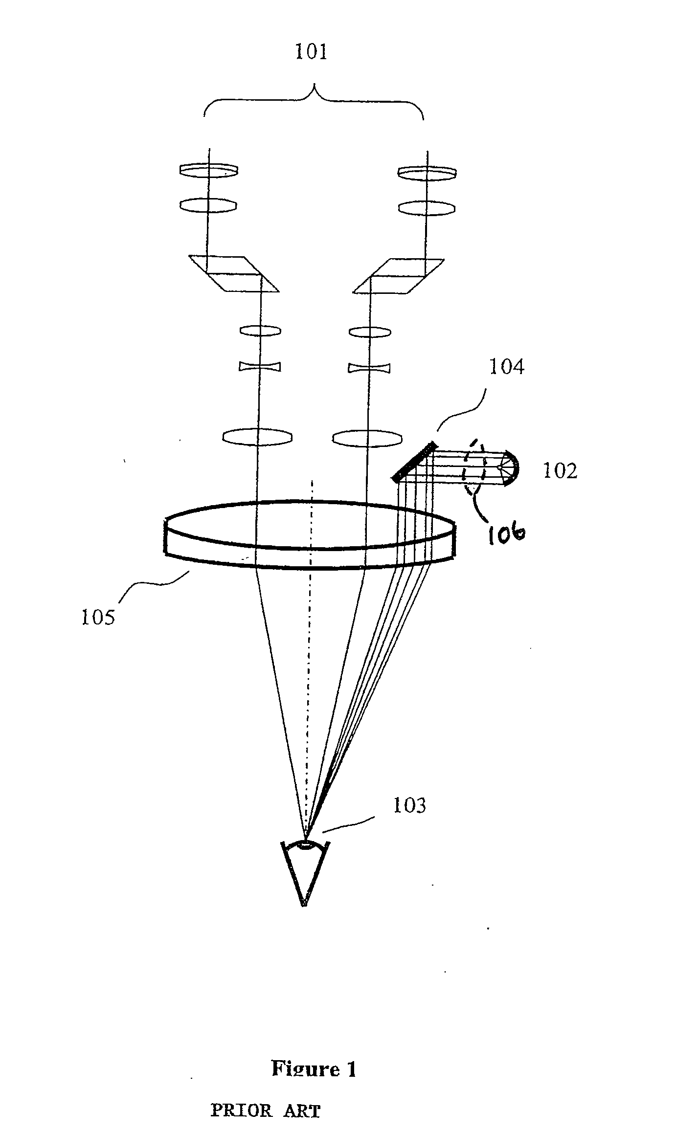
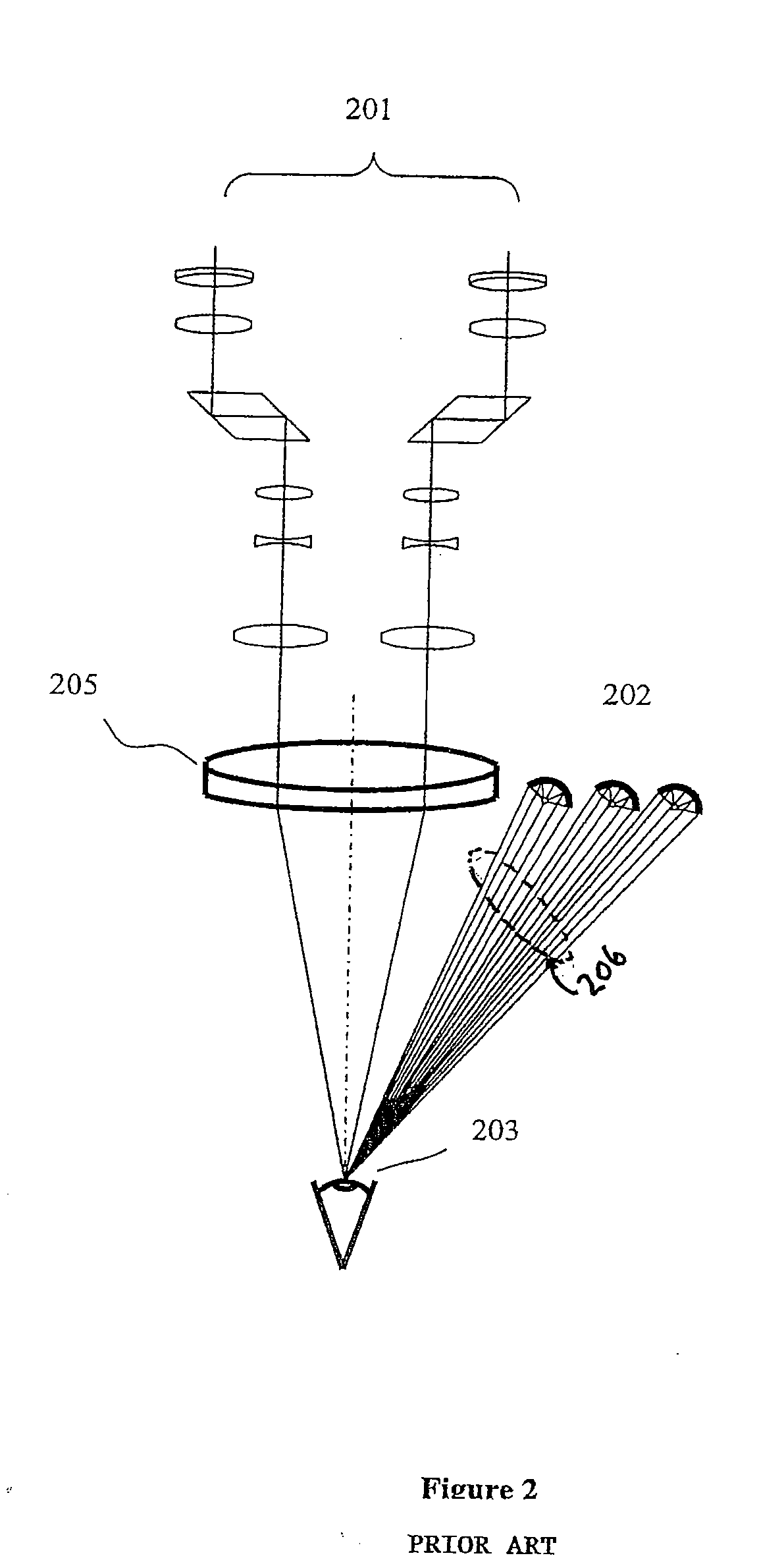
Direct illumination of this kind has several drawbacks, including the complexity of the opto-mechanical assembly and the need for individual beam alignment and aiming in three-dimensional space.

Method used


Image

  • Illumination System for Surgical Microscope
  • Illumination System for Surgical Microscope
  • Illumination System for Surgical Microscope

Examples


Embodiment Construction

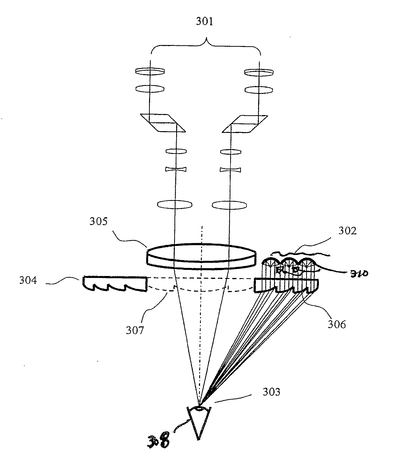
[0023]FIG. 3 is a schematic representation of an ophthalmic surgical microscope 301 with extended illumination source 302 forming an oblique illumination pattern at an eye plane 303 achieved through the aid of an auxiliary lens 304 in accordance with an embodiment of the present invention. Auxiliary lens 304 is a larger lens than the main objective lens 305.

[0024]The extended size illumination source with oblique illumination pattern at the eye plane 303 and reduced light density on the retina is obtained in this embodiment by arranging several individual smaller size light sources 310 in a specific pattern or cluster on a substrate such as a printed circuit board (PCB) to form a composite extended illumination source 302. The individual light sources 310 are preferably solid-state lighting devices such as light-emitting diodes (LEDs). Spectral composition of the LEDs is chosen based on desired illumination requirements. For surgical microscopes, including ophthalmic surgical micros...


PUM


Abstract

An illumination system and method of illuminating a surgical site are disclosed. One embodiment of the illumination system comprises: a composite illumination source, comprising a plurality of light sources operable to emit a plurality of collinear light beams; and an illumination lens, operable to receive and focus the plurality of light beams at a focal plane; wherein the plurality of collinear light beams are directed onto an off-axis portion of the illumination lens and wherein the illumination lens is aligned co-axially and confocally with an objective lens of an observation device. The light sources can be solid-state lighting devices, such as light-emitting diodes. The observation device can be a surgical ophthalmic microscope. The illumination lens can have a larger diameter than the objective lens, and the off-axis portion of the illumination lens can comprise a Fresnel type lens. The illumination lens can have a clear central portion of a diameter sufficient to prevent interference with the focusing function of the objective lens, or the illumination lens can comprise a ring with a central opening of a diameter sufficient to prevent interference with the focusing function of the objective lens.

Description

CROSS-REFERENCE TO RELATED APPLICATIONS[0001]This application claims priority under 35 U.S.C. §119 to U.S. Provisional Patent Application No. 60 / 868,959 filed Dec. 7, 2006, the entire contents of which are incorporated herein by reference.FIELD OF INVENTION[0002]The present invention relates to the field of surgical illumination. More specifically, it relates to illumination systems used in ophthalmic surgical microscopes to illuminate a surgical observation area. Even more specifically, the present invention relates to ophthalmic illumination systems that reduce the risk of injury to a patient's eye from a light source.BACKGROUND[0003]An illumination system is an integral and important part of a surgical microscope used to make visible the details of an object or area during surgery. Ophthalmic instruments, including ophthalmic surgical microscopes, not only require sufficient levels of irradiance at an object (e.g., the eye plane) for visualization purposes, but are also required ...

Claims


Application Information

Patent Timeline
Patent Type & Authority Applications(United States)
IPC IPC(8): G02B21/06
CPCA61B3/0008G02B21/082G02B21/0012A61B3/13
Inventor HOPLER, MARK D.CAMPIN, JOHN A.SOSKIND, YAKOV
Owner ALCON REFRACTIVEHORIZONS
Learn More