Communication System Resource Management Device Resource Management Method Communication Management Device and Communication Management Method

a communication management device and communication system technology, applied in the field of communication system resource management device resource management method communication management device, communication management device, communication management method, etc., can solve the problems of double-reservation of overlap, qos interruption, and insufficient rsvp support of mn movement, so as to facilitate the management of paths (particularly qos paths)

Inactive Publication Date: 2008-06-12
PANASONIC CORP
View PDF0 Cites 54 Cited by
  • Summary
  • Abstract
  • Description
  • Claims
  • Application Information

AI Technical Summary

Benefits of technology

[0120]In addition, the invention has the above-described configuration. The interdependency between the mechanism for establishing the state for routing the signaling message when the path related to the additional service (particularly the QoS) is established and the mechanism for making a resource reservation to provide the data packet with the additional service can be reduced. As a result, a smooth path (particul

Problems solved by technology

However, there is a problem in that the RSVP does not sufficiently support MN movement.
As a result, a QoS interruption occurs.
In this case, various problems may occur, such as a double-reservation of the overlapping paths and difficulty in path changes.
First, the first issue related to the conventional technology will be described.
However, the proxy may not be able to acquire the NCoA of the MN before the MN actually moves.
A smooth path establishment may be obstructed by the process of acquiring the NCoA in advance.
In this case, it

Method used


Image

  • Communication System Resource Management Device Resource Management Method Communication Management Device and Communication Management Method
  • Communication System Resource Management Device Resource Management Method Communication Management Device and Communication Management Method
  • Communication System Resource Management Device Resource Management Method Communication Management Device and Communication Management Method

Examples


first embodiment

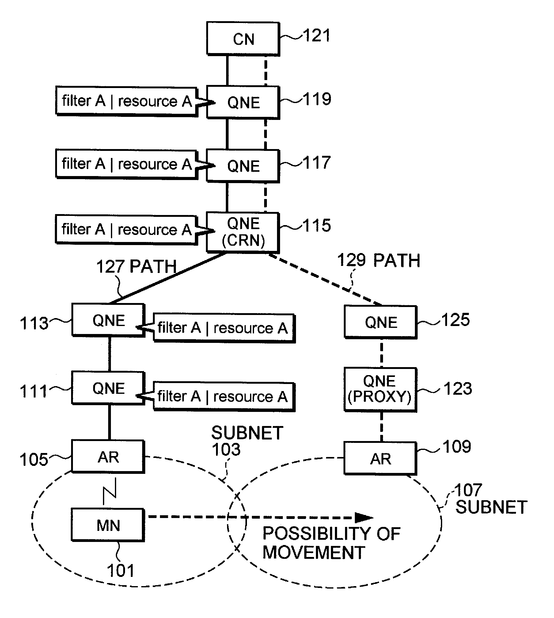
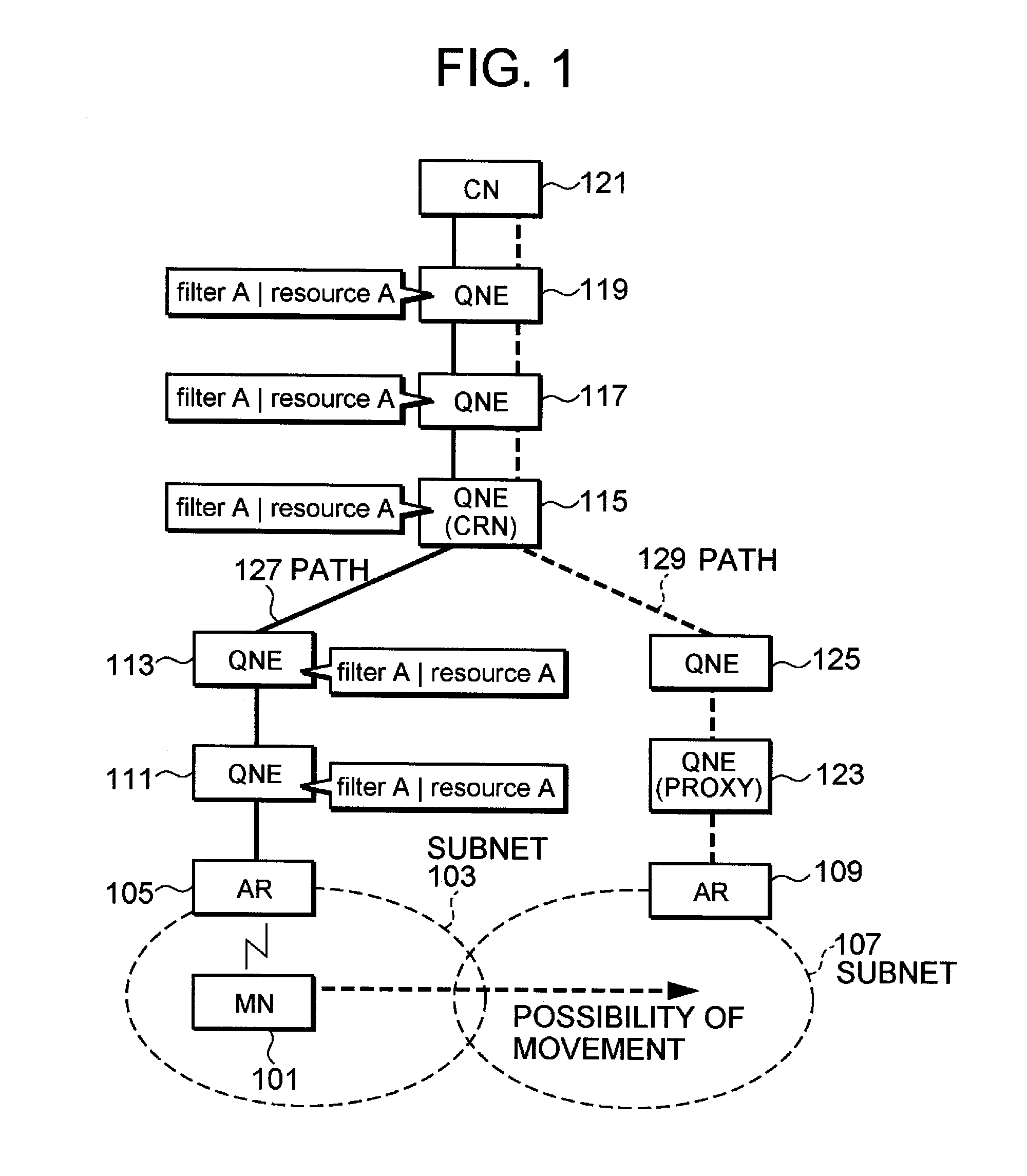
[0140]Hereafter, the first embodiment of the invention will be described. First, an overview according to the first embodiment of the invention will be described with reference to FIG. 1 to FIG. 3. FIG. 1 is a diagram schematically showing a state of a QoS path before a subset to which an MN is connected is changed in a communication system according to the first embodiment of the present invention. FIG. 2 is a diagram schematically showing a state in which a QNE to become a proxy of the MN establishes a predictive path in the communication system according to the first embodiment of the invention.

[0141]FIG. 3 is a diagram schematically showing a state in which the MN moves to the new subset and a new QoS path is established between the MN and a CN in the communication system according to the first embodiment of the invention.

[0142]FIG. 1 to FIG. 3 show a MN 101, a CN 121, an access router (AR) 105, an AR 109, a QNE 111, a QNE 113, a QNE 115, a QNE 117, a QNE 119, a QNE 123, and a Q...

second embodiment

[0171]Next, the second embodiment of the invention will be described. First, an overview according to the first embodiment of the invention will be described with reference to FIG. 6 to FIG. 8. FIG. 6 is a diagram schematically showing the state of the QoS path before the subset to which the MN is connected is changed in a communication system according to the second embodiment of the invention. FIG. 7 is a diagram schematically showing a state in which a QNE that is the proxy of the MN establishes the predictive path in the communication system according to the second embodiment of the invention. FIG. 8 is a diagram schematically showing a state in which the MN moves to a new subset and a new QoS path is established between the MN and the CN in the communication system according to the second embodiment of the invention.

[0172]As does FIG. 1 to FIG. 3, FIG. 6 to FIG. 8 shows the MN 101, the CN 121, the AR 105, the AR 109, the QNE 111, the QNE 113, the QNE 115, the QNE 117, the QNE 1...

third embodiment

[0195]Next, a third embodiment of the invention will be described. There is no clear difference between the filter information (the filter) and the flow ID in the above descriptions. However, functions of each QNE, signal message processing, and the like when the filter information and the flow ID are clearly defined will be described hereafter.

[0196]First, the filter information according to the third embodiment of the invention will be described. According to the third embodiment of the invention, the filter information is defined as information used by each QNE as a packet classifier. Similar to filter spec in the RSVP, the filter information is carried to each QNE as a parameter of the signaling message for making the QoS reservation. In other words, in the NSIS, the filter information is information mainly generated and managed in the NSLP. Each QNE stores the filter information with the information on the requested QoS resource information, thereby distinguishing to which data...


PUM


Abstract

An object is, when a mobile terminal performs a handover, to more quickly reset a path after the handover and reduce interrupt time (particularly interrupt time of a QoS path) of packet communication. For example, in a state in which a MN 101 has not acquired an address (NCoA) of a new connection destination (AR 109), the MN 101 requests that a QNE (proxy) 123 start a process of establishing a QoS path used when the MN 101 is connected to a new connection destination. The QNE (proxy) makes a resource reservation between the ONE (proxy) itself and a CN 121. As a result, in an upper stream above a QNE (CRN 115), new path information (filter B) is correlated with path information (filter A) used when the MN is connected to an AR 105. Until when the MN uses the actual new CoA and updates the QoS path after movement, the data packet is encapsulated by a proxy node and transmitted based on the path information (filter B).

Description

TECHNICAL FIELD[0001]The present invention relates to a communication system, a resource management device, a resource management method, a communication management device, and a communication management method. In particular, the present invention relates to a communication system, a resource management device, a resource management method, a communication management device, and a communication management method used in a communication network performing packet transfer.BACKGROUND ART[0002]A technology using a mobile internet protocol (IP) is becoming popular as a technology that can provide a user accessing a communication network, such as the Internet, from a mobile terminal through a wireless network with a seamless connection to the communication network, even during movement. The mobile IP is a next-generation internet protocol.[0003]At the same time, services such as a Quality of Service (QoS) guarantee (in the present specification, such services are referred to as additiona...

Claims


Application Information

Patent Timeline
IPC IPC(8): H04Q7/24H04W4/00H04W8/26H04W28/26H04W36/12H04W76/02
CPCH04L45/00H04L45/302H04W4/00H04W76/02H04W28/26H04W36/12H04W40/36H04W8/26H04W76/10
Inventor HORI, TAKAKOCHENG, HONGUE, TOYOKIHUANG, QIJIE
Owner PANASONIC CORP
Why Eureka
Try Eureka