Control System For Hybrid Vehicles

Active Publication Date: 2008-06-12
TOYOTA JIDOSHA KK
View PDF16 Cites 31 Cited by
  • Summary
  • Abstract
  • Description
  • Claims
  • Application Information

AI Technical Summary

Benefits of technology

[0025]According to the invention thus constructed, the load on the second hydraulic pump is accumulated on the basis of the amount of the operating oil to be generated by the second hydraulic pump, and the temperature thereof. In case the cumulative value exceeds the preset value, the halt of the first prime mover is inhibited and the oil pressure is generated by the first hydraulic pump. In the meantime, the

Problems solved by technology

Additionally, the limitation of the output torque of the second prime mover is lifted when the oil

Method used


Image

  • Control System For Hybrid Vehicles
  • Control System For Hybrid Vehicles
  • Control System For Hybrid Vehicles

Examples


Embodiment Construction

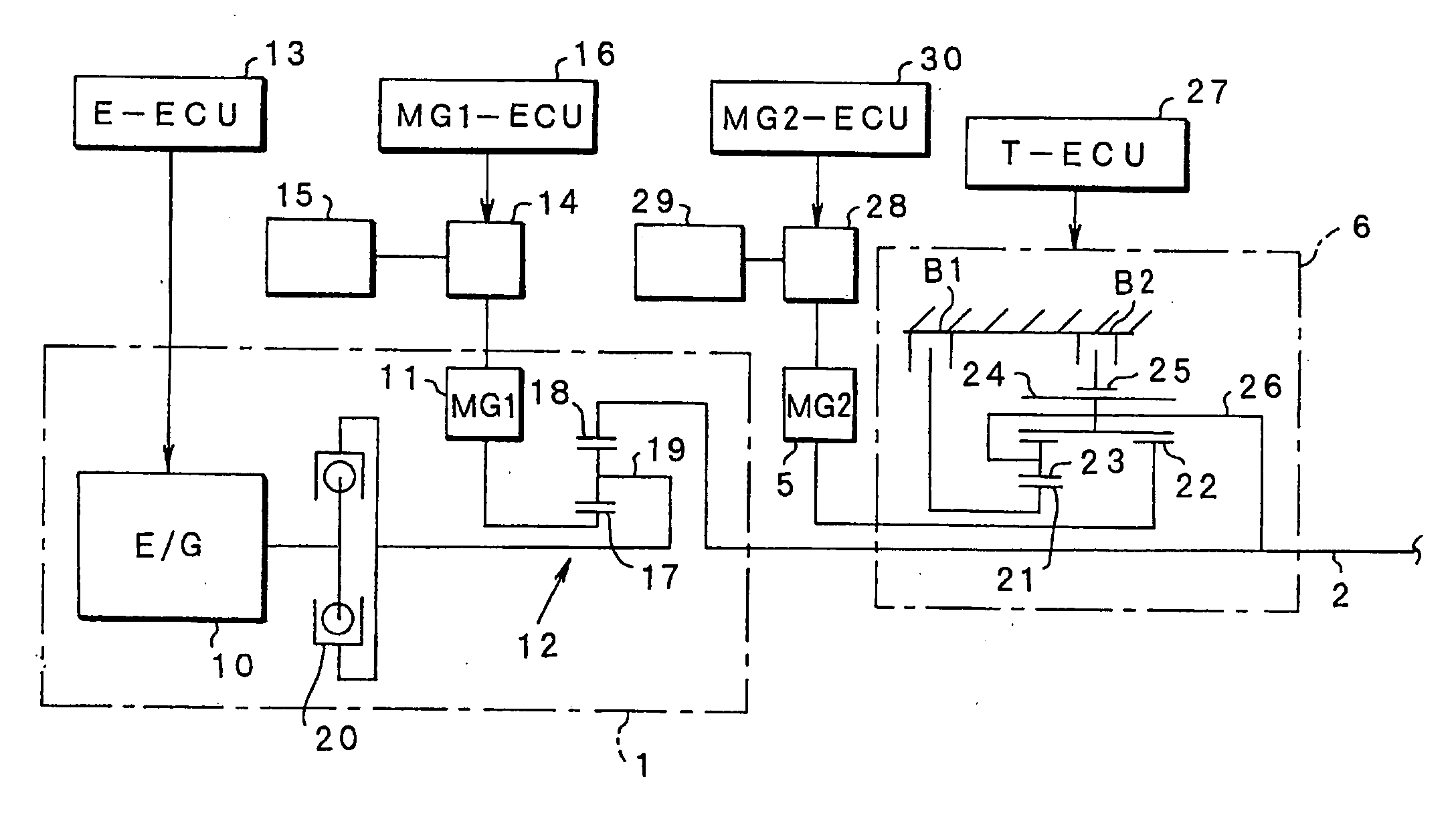
[0037]This invention will be described in connection with its specific examples. A hybrid drive unit to which this invention is applied will be, described first. The intended hybrid drive unit in this invention is, for example, mounted on a vehicle. As shown in FIG. 8, the torque of a main prime mover 1 (i.e., a first prime mover) is transmitted to an output member 2, from which the torque is transmitted through a differential 3 to drive wheels 4. On the other hand, there is provided an assist prime mover (i.e., a second prime mover) 5, which can make a power control to output a driving force for a drive and a regenerative control to recover energy. This assist prime mover 5 is connected through a transmission 6 to the output member 2. Between the assist prime mover 5 and the output member 2, therefore, the transmission torque capacity is increased / decreased according to a gear ratio to be set by the transmission 6.

[0038]This transmission 6 can be constructed to set the gear ratio a...


PUM


Abstract

A control system for hybrid vehicles, in which a second prime mover is connected to an output member to which a power is transmitted from a first prime mover through a transmission in which a torque capacity is varied in accordance with an oil pressure, and which has a first hydraulic pump driven by the first prime mover for establishing an oil pressure to be fed to the transmission, and a second hydraulic pump arranged in parallel with the first hydraulic pump and driven by an electric motor. A torque limiter limits an output torque of the second prime mover temporarily to a predetermined torque which is lower than a maximum output torque, at a starting time of the first prime mover.

Description

TECHNICAL FIELD[0001]This invention relates to a control system for a hybrid vehicle in which a second prime mover is connected through a transmission to an output member to which a power is transmitted from a first prime mover and, more particularly, to a control system for a hybrid vehicle which has a hydraulic pump driven by the first prime mover and another independent hydraulic pump driven by an electric motor, and which is constructed to operate the transmission by an oil pressure established by those hydraulic pumps.BACKGROUND ART[0002]One example of the hybrid vehicle equipped with a so called “mechanical distribution type drive unit” is disclosed in Japanese Patent Laid-Open No. 2002-225578, and a construction thereof will be described briefly hereafter. In the disclosed hybrid vehicle, an engine torque is inputted to a carrier of a single pinion type planetary gear mechanism which constitutes a distributing mechanism, a first motor generator is connected to a sun gear, and...

Claims


Application Information

Patent Timeline
IPC IPC(8): B60K6/20B60W10/04B60K1/02B60K6/445B60W20/00B60K6/54B60L50/16B60W10/06B60W10/08B60W10/30F02D29/00F02D29/02F16H3/72F16H61/00
CPCB60K1/02Y10T477/23B60K6/445B60L2240/423B60W10/08B60W2710/083F16H3/725F16H61/0031F16H2200/0034F16H2200/2007F16H2200/2023Y02T10/642F16H2312/14Y02T10/6239Y10T477/675B60K6/365Y02T10/62Y02T10/64
Inventor HAYASHI, KOJIITO, MASATOSHIENDO, HIROATSUOZEKI, TATSUYA
Owner TOYOTA JIDOSHA KK
Why Eureka
Try Eureka