Method and Apparatus for Determining Micro-Reflections in a Network

a micro-reflection and network technology, applied in the field of determining micro-reflections in a network, can solve the problems of micro-reflections of communication signals, large and complex networks, and difficult management and monitoring of cable operators, so as to optimize micro-reflection performance, optimize signal quality and network speed, and optimize the effect of network resources

Active Publication Date: 2008-06-12
ARRIS ENTERPRISES LLC
View PDF99 Cites 42 Cited by
  • Summary
  • Abstract
  • Description
  • Claims
  • Application Information

AI Technical Summary

Benefits of technology

[0020]Those of skill in the art will appreciate that the techniques of this invention allows an operator to automatically determine micro-reflections in upstream communication channels without the need for placing test instrumentation remotely in the cable plant. In addition, the technique discloses in the invention does not require an operator or technician to be dispatched to remote locations in the HFC network. All measurements may be made through the use of the existing terminal devices (specifically, DOCSIS terminal devices such as MTAs and cable modems) as well as headend equipment (specifically a DOCSIS CMTS). Accurate knowledge of the mirco-reflections will enable an operator to utilize the available resources of their network more efficiently, such as by switching to communication channels with fewer micro-reflections or by replacing network components in which the micro-reflections are introduced to improve signal quality and network speed.
[0021]Additionally, this process will optimize micro-reflection performance within the upstream HFC plant. This process uses only DOCSIS terminal devices in conjunction with measurements made at the headend via a DOCSIS CMTS device, and does not require rolling trucks to remote locations within a plant or specialized test equipment.

Problems solved by technology

The extensive and complex networks are often difficult for a cable operator to manage and monitor.
Any disruption of voice or data traffic is a great inconvenience and often unacceptable to a subscriber.
One factor that affects the quality of upstream communications is the presence of micro-reflections of communication signals.
There are two significant causes of micro-reflections in an upstream HFC plant, impedance mismatches and diplex filters.
Significant micro-reflections can degrade upstream HFC plant performance.
This diagnostic process requires extensive manual effort, often requiring rolling trucks to remote locations within a plant or specialized test equipment.
The diagnostic process is also time consuming and costly.

Method used


Image

  • Method and Apparatus for Determining Micro-Reflections in a Network
  • Method and Apparatus for Determining Micro-Reflections in a Network
  • Method and Apparatus for Determining Micro-Reflections in a Network

Examples


Embodiment Construction

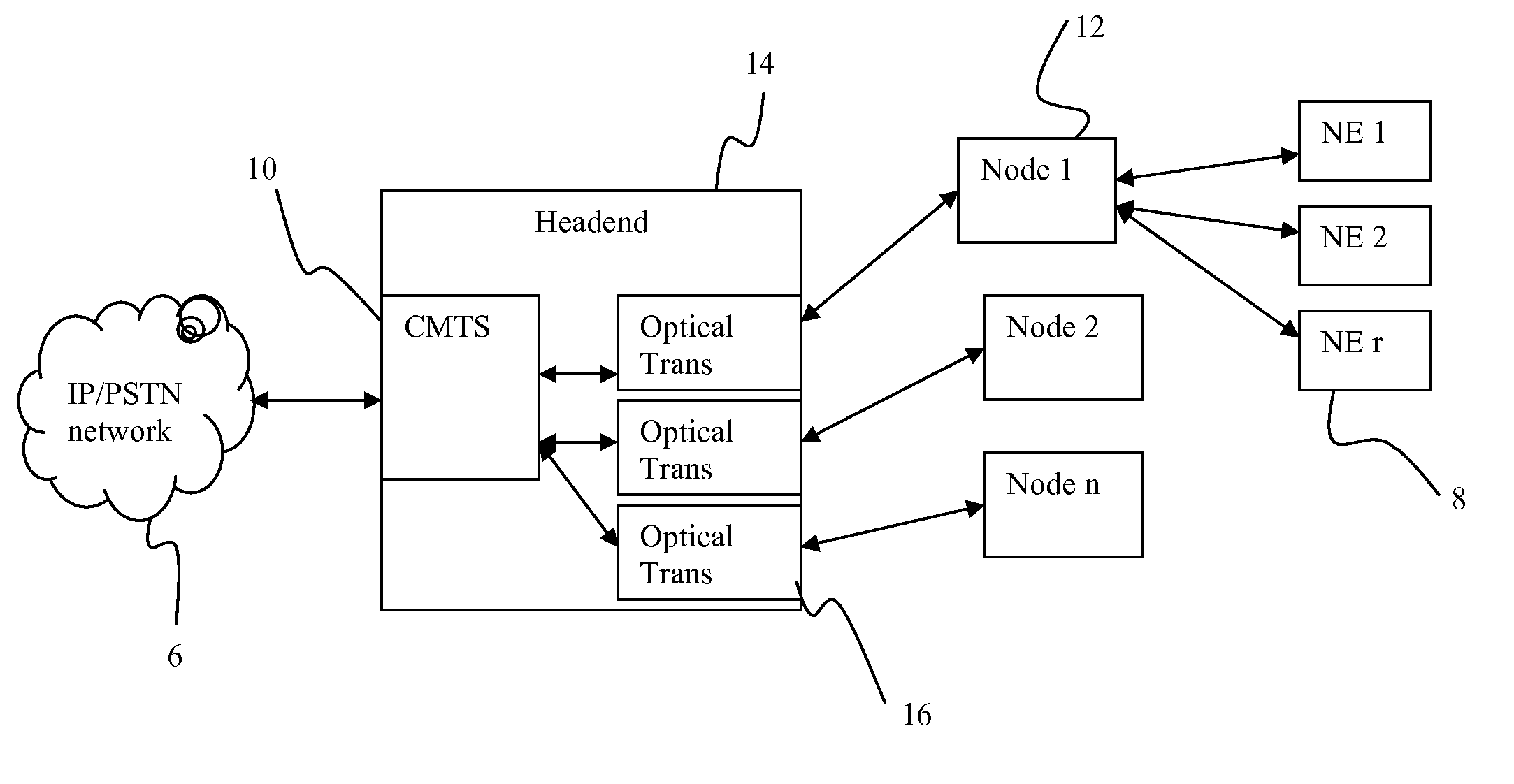
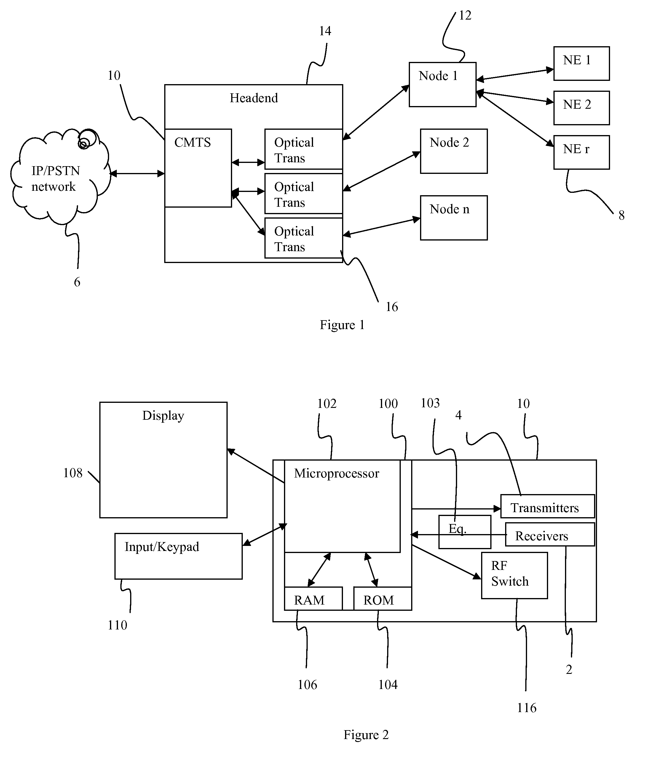
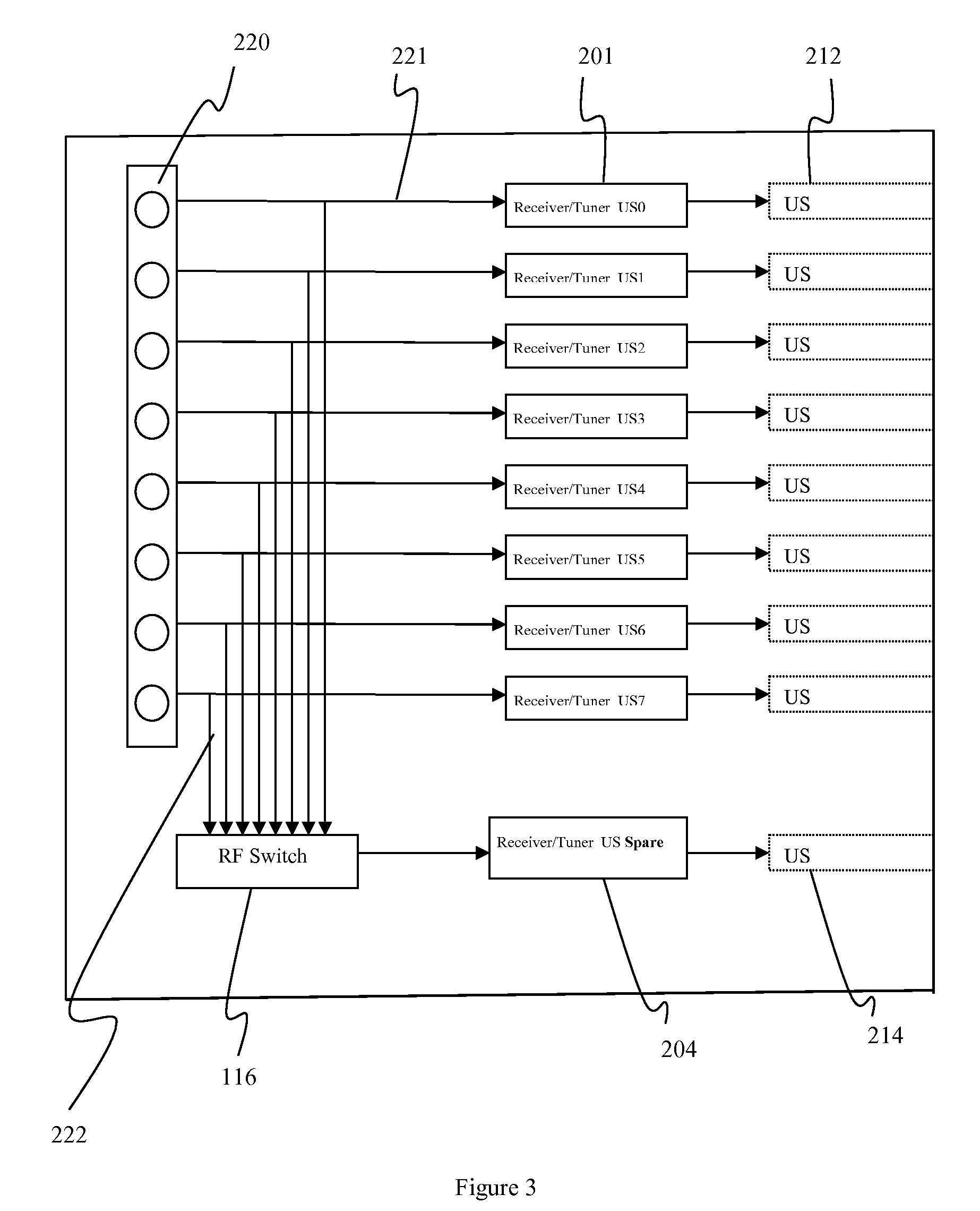
[0030]This disclosure provides for remote assessment of micro-reflections for terminal devices within a CMTS serving group as well as a means for optimally reassigning serving groups to active channels with improved micro-reflection performance. The micro-reflection assessment of all network elements, such as cable modems, set top boxes and media terminal adapter (MTAs) and DOCIS (data over cable system) terminal devices, within a CMTS serving group may provide a mapping of micro-reflection levels over all active channels available to the network elements. This methodology begins by querying network elements within a CMTS serving group to obtain their micro-reflection performance over a range of active channels. The micro-reflection mappings are used to determine optimum active channels, which are defined as channels which have the least amount of worst-case micro-reflections present. To assess the full extent of micro-reflection conditions that may exist with a upstream HFC plant, ...


PUM


Abstract

The presence of micro-reflections is determined in a network by determining micro-reflections from amplifier and diplex filter impedance mismatches and micro-reflections from drop cable impedance mismatches. The micro-reflections from impedance mismatches are determined by instructing network element to transmit a test signal at a first symbol rate and a first resolution for amplifier and diplex filter impedance mismatches and a second frequency with a second symbol rate and second resolution for micro-reflections from drop cable impedance mismatches. The tests are performed with several frequencies and the channels with the least micro-reflections are identified.

Description

FIELD OF THE INVENTION[0001]This disclosure is directed toward determining micro-reflections in a network. More particularly, this disclosure is directed toward determining micro-reflections in upstream communications in a HFC network to allow an optimal selection of transmission channels.BACKGROUND OF THE INVENTION[0002]Coaxial cable television systems have been in widespread use for many years and extensive networks have been developed. The extensive and complex networks are often difficult for a cable operator to manage and monitor. A typical cable network generally contains a headend which is usually connected to several nodes which provide content to a cable modem termination system (CMTS) containing several receivers, each receiver connects to several modems of many subscribers, e.g., a single receiver may be connected to hundreds of modems. In many instances several nodes may serve a particular area of a town or city. The modems communicate to the CMTS via upstream communicat...

Claims


Application Information

Patent Timeline
Patent Type & Authority Applications(United States)
IPC IPC(8): G06F15/173
CPCH04L12/2697H04M1/24H04L43/50G06F15/173H04L12/28
Inventor THOMPSON, ROBERT J.COOPER, MICHAEL J.MOORE, CHARLES S.MORAN, JOHN L.
Owner ARRIS ENTERPRISES LLC
Why Eureka
Try Eureka