Recovery cup cleaning method and substrate treatment apparatus

a cleaning method and substrate technology, applied in the field of recovery cup cleaning method, to achieve the effect of suppressing the ingress of cleaning liquid

Inactive Publication Date: 2008-06-19
DAINIPPON SCREEN MTG CO LTD
View PDF2 Cites 53 Cited by
  • Summary
  • Abstract
  • Description
  • Claims
  • Application Information

AI Technical Summary

Benefits of technology

[0014]It is an object of the present invention to provide a recovery cup cleaning method which suppresses ingress of a c

Problems solved by technology

Therefore, even if the interior wall of the recovery space is cleaned with the cleaning liqui

Method used


Image

  • Recovery cup cleaning method and substrate treatment apparatus
  • Recovery cup cleaning method and substrate treatment apparatus
  • Recovery cup cleaning method and substrate treatment apparatus

Examples


first embodiment

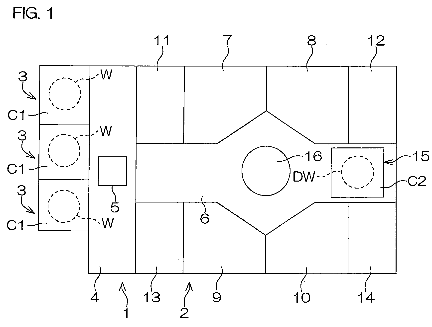
[0039]FIG. 1 is a schematic plan view showing the layout of a substrate treatment apparatus according to one embodiment (first embodiment) of the present invention. The substrate treatment apparatus is of a single substrate treatment type which is adapted to treat semiconductor wafers W one by one (such a semiconductor wafer is an example of a substrate and hereinafter referred to simply as “wafer”). The substrate treatment apparatus includes an indexer section 1, a substrate treatment section 2 connected to one side of the indexer section 1, and a plurality of cassette holders 3 (three cassette holders 3 in this embodiment) aligned on the other side of the indexer section 1 (opposite from the substrate treatment section 2). Cassettes C1 in which a plurality of wafers Ware stored in a stacked state are respectively disposed on the cassette holders 3. Examples of the cassettes C1 include a FOUP (Front Opening Unified Pod) which is configured to store a plurality of wafers W in a seal...

second embodiment

[0114]FIGS. 8(a) to 8(c) are partial sectional views schematically showing positional relationships between the spin chuck 20 and the recovery cup 200 during the treatment of the wafer W to be performed by the substrate treatment apparatus according to the

[0115]When the upper edge portion 112b of the outer structural member 112 is located at a higher level than the wafer W held by the spin chuck 20 and the upper edge portion 125b of the first guide portion 125 of the inner structural member 110 and the upper edge portion 148b of the second guide portion 148 of the intermediate structural member 111 are located at lower levels than the wafer W (see FIG. 8(a)), an opening is defined between the upper edge portion 148b of the second guide portion 148 and the upper edge portion 112b of the outer structural member 112 as being opposed to the peripheral surface of the wafer W. With the structural members 110 to 112 of the recovery cup 200 located in such a positional relationship, the waf...


PUM


Abstract

An inventive recovery cup cleaning method is a method for cleaning a recovery cup having an interior wall partitioning a recovery space into which a chemical agent used for treating a substrate is introduced, the recovery cup being configured such that the chemical agent introduced into the recovery space is further introduced into a predetermined chemical agent recovery passage so as to be recovered. The method comprises the steps of: cleaning the interior wall of the recovery space with a cleaning liquid; cleaning the interior wall of the recovery space with a chemical cleaning agent after the step of cleaning with the cleaning liquid, the chemical cleaning agent being of the same type as the chemical agent to be recovered through the recovery space; and draining the cleaning liquid introduced into the recovery space in the step of cleaning with the cleaning liquid and the chemical cleaning agent introduced into the recovery space in the step of cleaning with the chemical cleaning agent through a drain passage which is different from the chemical agent recovery passage.

Description

BACKGROUND OF THE INVENTION[0001]1. Field of the Invention[0002]The present invention relates to a recovery cup cleaning method for cleaning a recovery cup into which a chemical agent used for treatment of a substrate is introduced, and a substrate treatment apparatus employing the recovery cup cleaning method. Examples of the substrate to be treated include semiconductor wafers, glass substrates for liquid crystal display devices, glass substrates for plasma display devices, substrates for FED (Field Emission Display) devices, substrates for optical disks, substrates for magnetic disks, substrates for magneto-optical disks, and substrates for photo masks.[0003]2. Description of Related Art[0004]In production processes for semiconductor devices and liquid crystal display devices, substrate treatment apparatuses of a single substrate treatment type are used for treating a surface of a substrate (e.g., a semiconductor wafer or a glass substrate for a liquid crystal display panel) with...

Claims


Application Information

Patent Timeline
IPC IPC(8): B08B9/08B08B3/08B08B13/00G03F1/82G11B5/84G11B7/26H01L21/027H01L21/304H01L21/306
CPCH01L21/67023H01L21/6708H01L21/67051H01L21/02H01L21/304
Inventor HASHIZUME, AKIO
Owner DAINIPPON SCREEN MTG CO LTD
Why Eureka
Try Eureka