Method and apparatus for heating a substrate

a technology of heating apparatus and substrate, which is applied in the direction of heating arrangements of hot plates, lighting and heating apparatus, furniture, etc., can solve the problems of not being able to achieve rapid dynamic control of fluid temperature to compensate for rapid substrate temperature fluctuations, and the response time required to bring the substrate to a desired temperature is relatively long

Inactive Publication Date: 2008-06-19
APPLIED MATERIALS INC
View PDF4 Cites 7 Cited by
  • Summary
  • Abstract
  • Description
  • Claims
  • Application Information

AI Technical Summary

Benefits of technology

[0012]In another aspect of the invention, a method for heating a substrate is provided. In one embodiment, a method of heating a substrate includes placing a substrate on a support member of a substrate heater comprising a vessel partially filled with a liquid; and boiling the liquid to create a film of condensation on a bottom side of the support member. Optionally, the pressure inside the vessel may be controlled. Optionally, the energy phase of the liquid disposed within the vessel may be controlled.

Problems solved by technology

Changes in, and gradients across the substrate surface during substrate processing are detrimental to material deposition, etch rate, feature taper angles, step coverage, and the like.
This method of cooling the substrate has two inherent problems.
First, the response time required to bring a substrate to a desired temperature is relatively long.
As such, rapid dynamic control of the fluid temperature to compensate for rapid substrate temperature fluctuations is not possible.
Consequently, the substrate is not maintained at a desired temperature.
A second disadvantage of this method is the inability to control the temperature profile across the surface of the substrate, particularly where a uniform temperature profile is desired.
This temperature gradient is one of the primary causes of feature variation in semiconductor substrate processing.
Such gradients between a plurality of devices cause substantial temperature variation across the substrate, i.e., hot and cold locations are formed.
Additionally, the high bias power (up to and exceeding 1000 Watts) applied to electrostatic chucks used in etching some materials contribute significantly to the heat load upon the substrate, requiring further cooling of the substrate.

Method used


Image

  • Method and apparatus for heating a substrate
  • Method and apparatus for heating a substrate
  • Method and apparatus for heating a substrate

Examples


Embodiment Construction

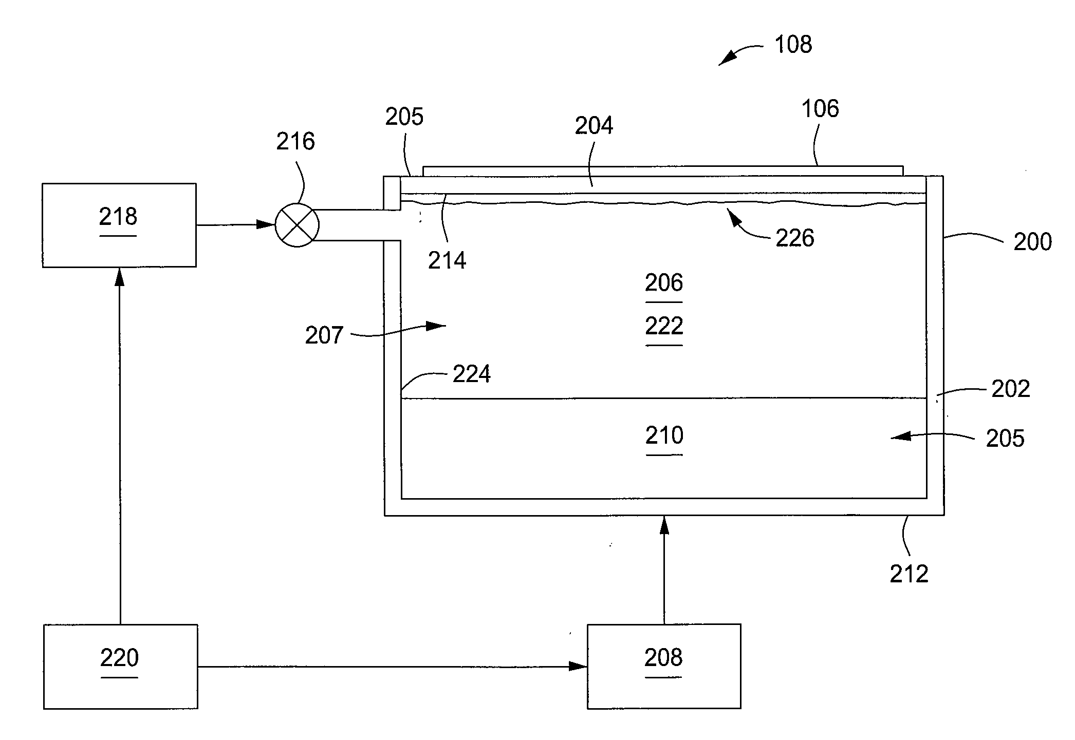
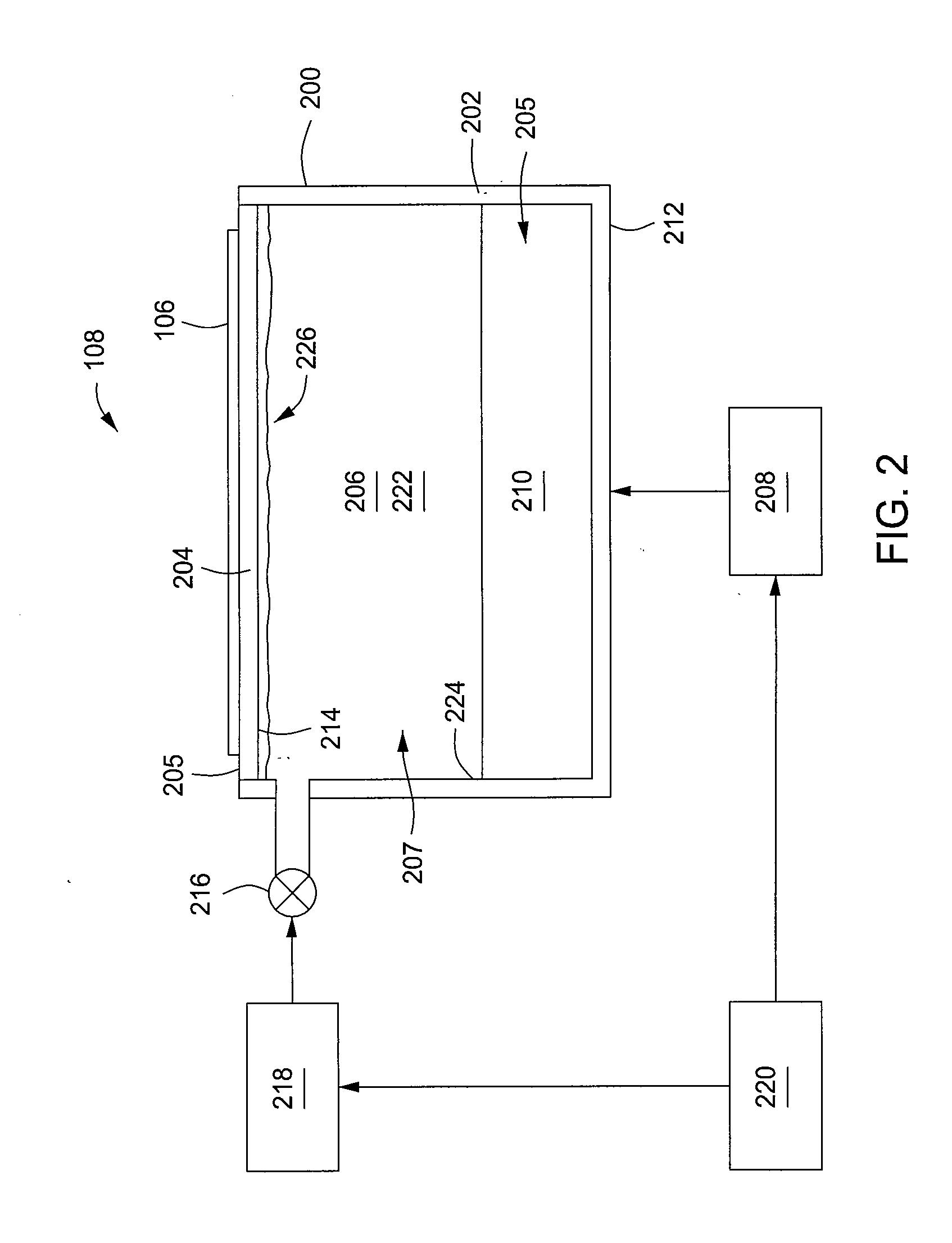
[0019]The present invention provides a method and apparatus for heating a substrate utilizing a simultaneous presence of liquid and gas on the underside of a heat transfer solid to establish a controlled temperature buffer zone. The heating apparatus employs a vessel containing a liquid which, when boiling, creates a substantially uniform film of condensation on the bottom of a substrate support surface. The film of condensation is heated by the condensation of the vapor phase, thereby heating the substrate support surface, and a substrate disposed thereon. Evaporation of portions of the film of condensation removes heat from the film of condensation, thereby facilitating the maintenance of a substantially uniform temperature of the condensate, and ultimately, the substrate. The exchange of heat which occurs during the phase change of the fluid on the support underside occurs at a constant temperature, that of the vapor-liquid equilibrium temperature for the fluid. In embodiments wh...


PUM


Abstract

A method and apparatus for heating a substrate is provided herein. In one embodiment, a substrate heater includes a vessel having an upper member including a top surface for supporting a substrate thereon; a liquid disposed within and partially filling the vessel; and a heat source for providing sufficient heat to the liquid to boil the liquid. Optionally, a pressure controller for regulating the pressure within the vessel may be provided. The substrate is heated by first placing the substrate on the support surface of the vessel of the substrate heater. The liquid contained in the vessel is then boiled. As the liquid is boiling, a uniform film of heated condensation is deposited on a bottom side of the support surface. The heated condensation heats the support surface which in turn, heats the substrate.

Description

BACKGROUND OF THE INVENTION[0001]1. Field of the Invention[0002]Embodiments of the present invention generally relate to a method and apparatus for heating a substrate. More specifically, the present invention relates to heating a substrate using a simultaneous presence of liquid and gas on the underside of a heat transfer solid to establish a controlled temperature buffer zone.[0003]2. Description of the Related Art[0004]In semiconductor substrate processing, the surface temperature of the substrate is often a critical process parameter. Changes in, and gradients across the substrate surface during substrate processing are detrimental to material deposition, etch rate, feature taper angles, step coverage, and the like. It is often desirable to have control over a substrate temperature profile before, during, and after substrate processing to enhance processing and minimize undesirable characteristics and / or defects.[0005]A number of devices have been used in the art to control subs...

Claims


Application Information

Patent Timeline
Patent Type & Authority Applications(United States)
IPC IPC(8): H01L21/00H05B3/02F28D15/02F28F27/00
CPCF28D15/02F28D15/06H01L21/67109F28F13/14F28F13/185F28D2021/0077H01L21/322
Inventor RANISH, JOSEPH M.ADAMS, BRUCE E.HUNTER, AARON M.
Owner APPLIED MATERIALS INC
Why Eureka
Try Eureka