Current-perpendicular-to-plane sensor with dual keeper layers

a sensor and perpendicular-to-plane technology, applied in the field of current perpendicular-to-plane sensor with dual keeper layers, can solve the problems of reducing the strength of antiparallel coupling when applied to the surface, deteriorating microstructural effects, and destroying the desired unidirectional anisotropy, so as to achieve the effect of maximizing the tmr

Inactive Publication Date: 2008-06-19
WESTERN DIGITAL TECH INC
View PDF21 Cites 26 Cited by
  • Summary
  • Abstract
  • Description
  • Claims
  • Application Information

AI Technical Summary

Benefits of technology

[0039]With reference now to FIG. 7, an advantage of the invention is a substantial reduction in a ferromagnetic coupling field (HF). FIG. 7 shows HF versus barrier layer thickness. Indeed, HF is substantially reduced when a Co—Fe—B alloy film replaces a Co—Fe alloy film as a keeper layer. As a result, a thinner barrier layer can be used, leading to a lower junction resistance-area product (RJAJ). A smoother barrier layer can, therefore, be attained, leading to a higher TMR coefficient. AP pinning is weak in this structure. However, with modified composition of the Co—Fe—B keeper layer the AP pinning can be improved. Alternatively, the AP pinning can be improved by using a crystalline Co—Fe alloy layer on top of the Co—Fe—B alloy keeper layer in a dual keeper layer structure, as in an embodiment of the invention.
is a substantial reduction in a ferromagnetic coupling field (HF). FIG. 7 shows HF versus barrier layer thickness. Indeed, HF is substantially reduced when a Co—Fe—B alloy film replaces a Co—Fe alloy film as a keeper layer. As a result, a thinner barrier layer can be used, leading to a lower junction resistance-area product (RJAJ). A smoother barrier layer can, therefore, be attained, leading to a higher TMR coefficient. AP pinning is weak in this structure. However, with modified composition of the Co—Fe—B keeper layer the AP pinning can be improved. Alternatively, the AP pinning can be improved by using a crystalline Co—Fe alloy layer on top of the Co—Fe—B alloy keeper layer in a dual keeper layer structure, as in an

Problems solved by technology

However, this smoothing technique has the following drawbacks: it deteriorates microstructural effects when applied to the surface of the Ru seed layer; interrupts the growth of the preferred crystalline texture when applied to the Ir—Mn alloy pinning layer; destroys the desired unidirectional anisotropy when applied to the interface at the Ir—Mn alloy pinning layer; reduces the strength of antiparallel coupling when applied to surfaces of the Co—Fe alloy keeper and Ru spacer layers; and, diminishes tunneling effects when applied to the surface of the Co—Fe—B alloy reference layer.
In other words, this smoothing technique is not feasible.

Method used


Image

  • Current-perpendicular-to-plane sensor with dual keeper layers
  • Current-perpendicular-to-plane sensor with dual keeper layers
  • Current-perpendicular-to-plane sensor with dual keeper layers

Examples


Embodiment Construction

[0024]The following is a description of various embodiments presently contemplated for carrying out this invention. This description is made for the purpose of illustrating the general principles of this invention and is not meant to limit the inventive concepts claimed herein.

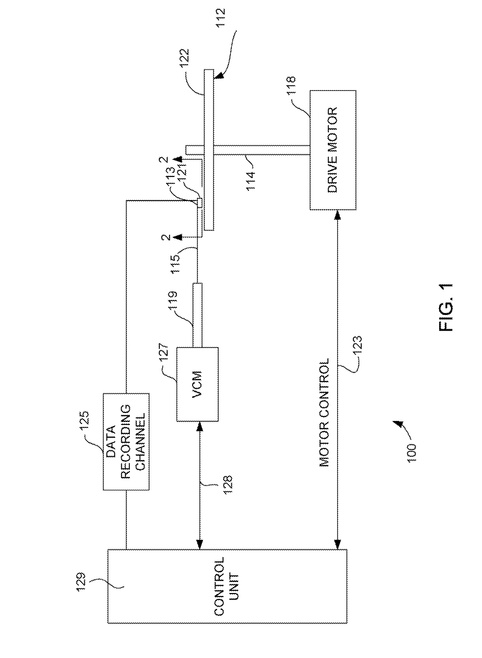
[0025]Referring now to FIG. 1, there is shown a magnetic disk drive 100 embodying this invention. As shown in FIG. 1, at least one rotatable magnetic disk 112 is supported on a spindle 114 and rotated by a disk drive motor 118. The magnetic recording is performed on each magnetic disk 112.

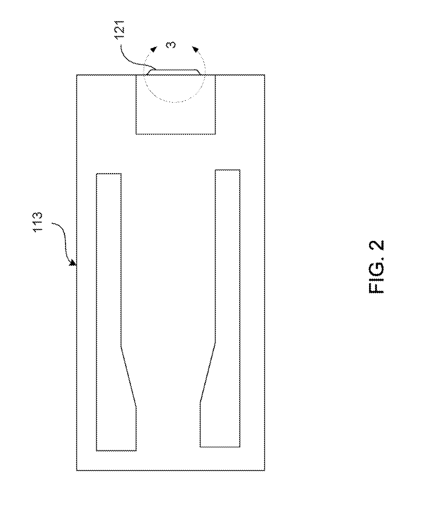
[0026]At least one slider 113 is positioned near the magnetic disk 112, each slider 113 supporting write and read heads 121. As the magnetic disk 112 rotates, the slider 113 moves radially in and out over the disk surface 122 so that the write and read heads 121 may access different tracks of the magnetic disk 112. Each slider 113 is attached to an actuator arm 119 by way of a suspension 115. The suspension 115 provides a sli...


PUM

PropertyMeasurementUnit
thicknessaaaaaaaaaa
thickaaaaaaaaaa
thickaaaaaaaaaa

Abstract

This invention provides a CPP TMR or GMR sensor with an amorphous ferromagnetic lower keeper layer and a crystalline ferromagnetic upper keeper layer. The amorphous ferromagnetic lower keeper layer strongly exchange-couples to an underlying antiferromagnetic pinning layer and planarizes its rough surface. The crystalline ferromagnetic upper keeper layer strongly antiparallel-couples to an adjacent ferromagnetic reference layer across a nonmagnetic spacer layer. The amorphous ferromagnetic lower keeper layer is preferably made of a Co—Fe—B alloy film with an Fe content high enough to ensure strong exchange-coupling to the underlying antiferromagnetic pinning layer, and with a B content high enough to ensure the formation of an amorphous phase for planarizing an otherwise rough surface due to the underlying antiferromagnetic pinning layer. The crystalline ferromagnetic upper keeper layer is preferably made of a Co—Fe alloy film with an Fe content low enough to ensure strong antiparallel-coupling to the adjacent ferromagnetic reference layer across the nonmagnetic spacer layer. The sensor is annealed at temperatures low enough to prevent the amorphous phase from transforming into a polycrystalline phase, but also high enough to maximize TMR.

Description

FIELD OF THE INVENTION[0001]The present invention relates to a current-perpendicular-to-plane (CPP) tunneling magnetoresistance (TMR) or giant magnetoresistance (GMR) sensor, and more particularly to a CPP TMR or GMR sensor that has multiple keeper layers.BACKGROUND OF THE INVENTION[0002]The heart of a computer is a non-volatile storage device that is referred to as a magnetic disk drive. The magnetic disk drive includes a magnetic disk, and write and read heads. The write and read heads are supported by a slider that is mounted on a suspension arm. When the magnetic disk rotates, an actuator swings the suspension arm to place the write and read heads over selected circular tracks on the surface of the rotating magnetic disk. An air flow generated by the rotation of the magnetic disk causes an air bearing surface (ABS) of the slider to fly at a very low elevation (fly height) over the surface of the rotating magnetic disk. The write and read heads write magnetic transitions to and r...

Claims


Application Information

Patent Timeline
Patent Type & Authority Applications(United States)
IPC IPC(8): G11B5/33G11B5/127
CPCB82Y25/00G01R33/093H01F10/3272G11B5/3932H01F10/3254G11B5/3906
Inventor LIN, TSANN
Owner WESTERN DIGITAL TECH INC
Why Eureka
Try Eureka