
Stereo-Based Visual Odometry Method and System

Active Publication Date: 2008-06-19
SRI INTERNATIONAL
View PDF4 Cites 108 Cited by
  • Summary
  • Abstract
  • Description
  • Claims
  • Application Information

AI Technical Summary

Benefits of technology

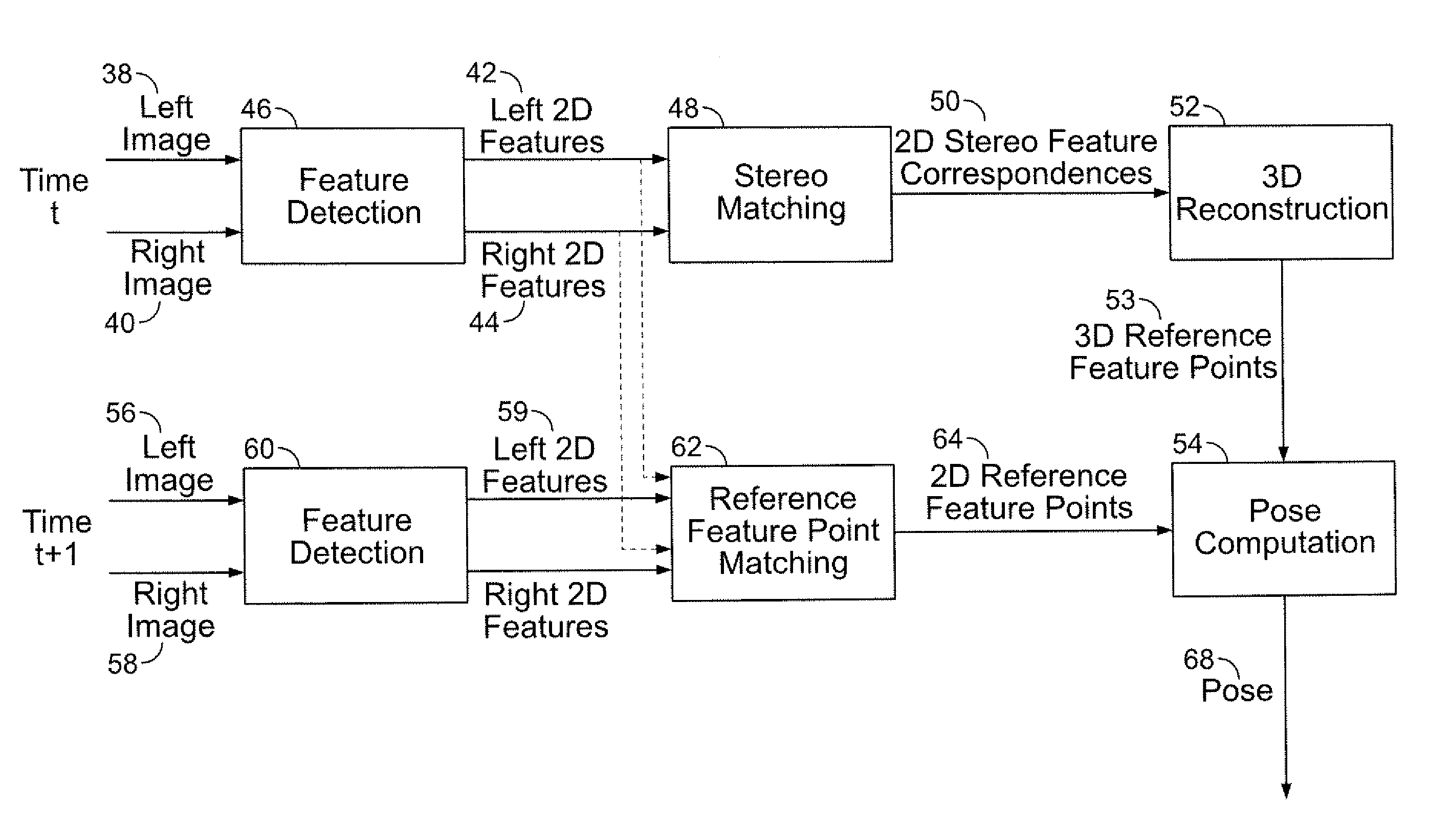
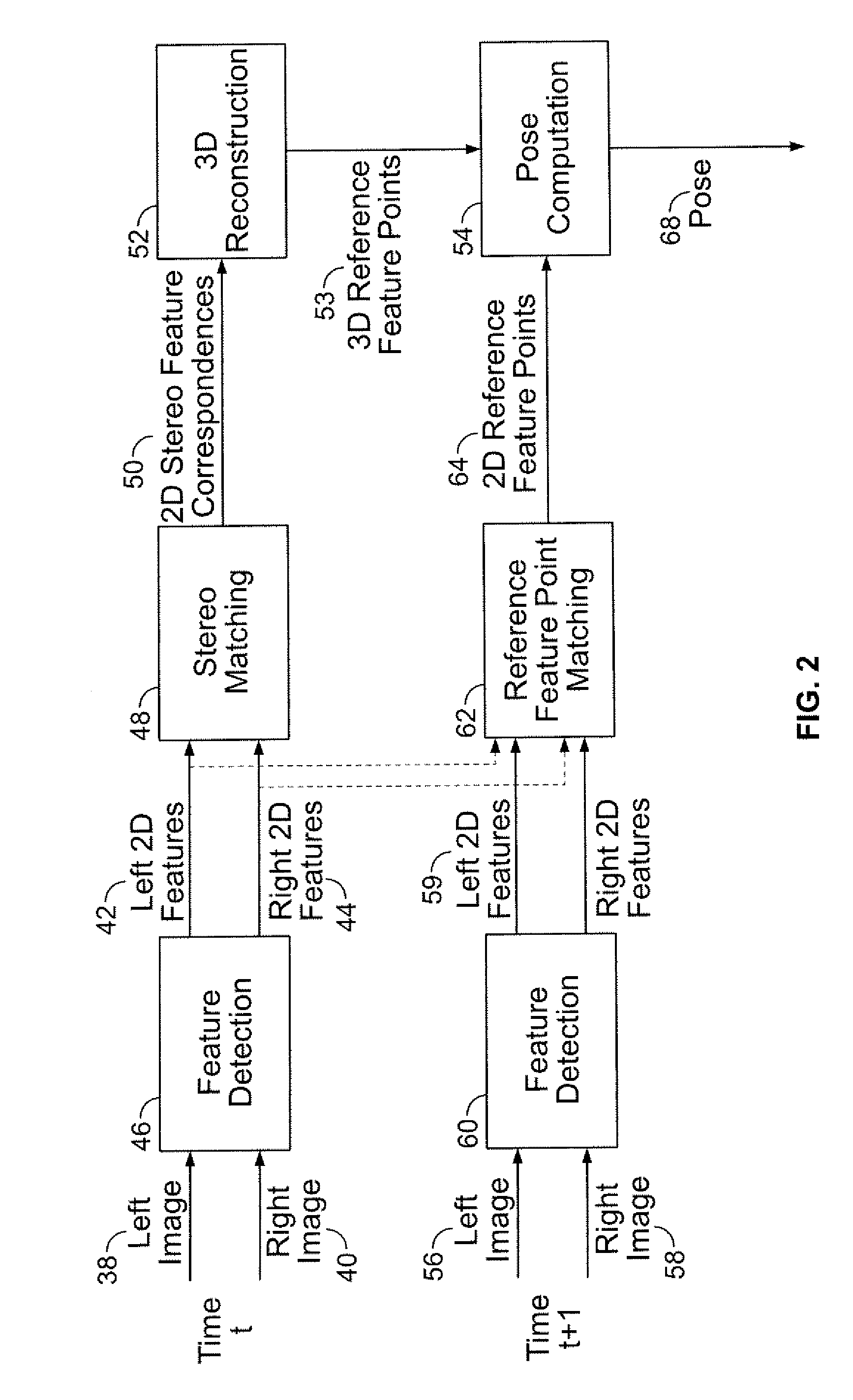
[0012]The pose is found by minimizing projection residuals of a set of 3D reference feature points in an image plane. Feature points correspond to Harris corners. The at least three three-dimensional feature points are found by triangulating the at least three two-dimensional feature correspondence from both the left image and the right image. Tracking of the at least three feature points is accomplished by detecting at least three feature points in both the left image and right image of the second pair of stereo images at the second point of time and matching the at least three feature points in one of the left image and right image of the first pair of stereo images to a corresponding one of the left image and the right image of the second stereo pair.

Problems solved by technology

Unfortunately, many existing navigation systems do not function very well under certain circumstances.
In certain circumstances, however, GPS cannot work reliably if the satellite signals upon which it is based are blocked or unavailable as often occurs in indoor environments, in forests, and in urban areas.
Even when it works well, GPS can only provide the location of the user, which is usually not sufficient to assist the user during navigation.
The latter technique has problems with stability, therefore, visual odometry systems based on stereo have been favored over monocular-based visual odometry systems.
A visual odometry system can often drift over time due to errors associated with stereo calibration or image quantization, poor-quality images, inaccurate feature positions, outliers, and instability of motion estimation using noisy correspondences.
However, prior art multi-frame tracking approaches lack a metric to stop tracking when the tracked feature points become insufficient for pose estimation in terms of either quantity or spatial distribution.
However, in some stereo-based visual odometry systems, during stereo matching, no stereo geometric constraints are utilized to reduce the search region and a large amount of false stereo matches results.
If features in moving objects are selected during pose estimation, these features can negatively affect the accuracy of the resulting pose unless they are detected and discarded as outliers.
In a nearly polar opposite scenario, there are situations where accuracy may degrade due to lack of features in the scene.

Method used


Image

  • Stereo-Based Visual Odometry Method and System
  • Stereo-Based Visual Odometry Method and System
  • Stereo-Based Visual Odometry Method and System

Examples


Embodiment Construction

[0018]The following embodiments are intended as exemplary, and not limiting. In keeping with common practice, figures are not necessarily drawn to scale.

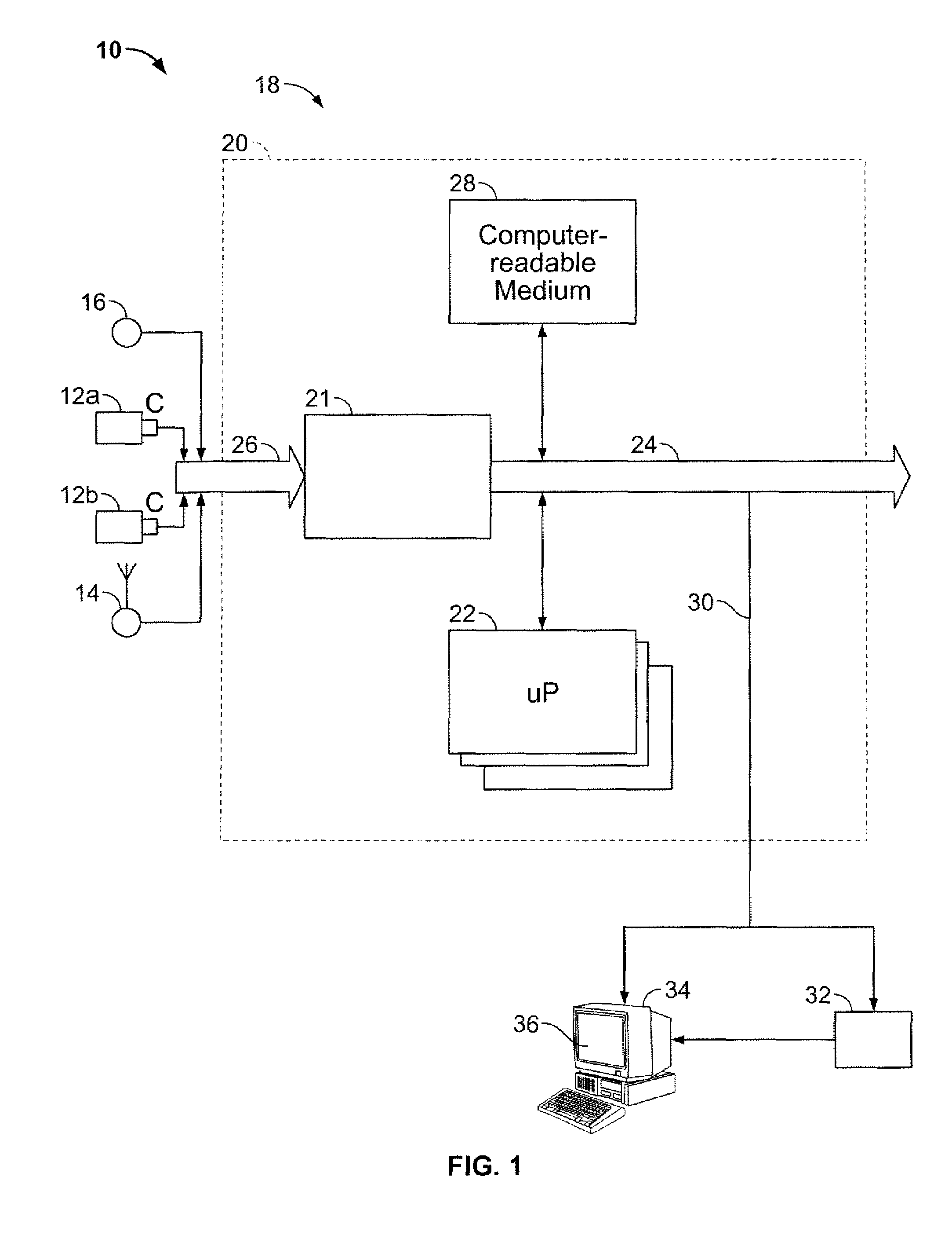
[0019]Referring now to FIG. 1, a stereo-based visual odometry system is depicted, generally indicated at 10. By way of a non-limiting example, the system 10 receives digitized video from a pair of stereo images originating from a stereo camera or a pair of monocular cameras configured as a stereo camera 12a, 12b, which may be rigidly mounted on a frame relative to each other and designed to cover overlapping fields of view. The camera(s), 12a, 12b, have been calibrated to determine their intrinsic parameters and the rigid transformation between the two images. To capture positions in real world coordinates, the system 10 may be equipped with a global positioning system receiver (GPS) 14. The system 10 may also be equipped with an inertial measurement unit (IMU) 16 (e.g., a CloudCap Crista) to capture the orientation of the measureme...


PUM


Abstract

A method for estimating pose from a sequence of images, which includes the steps of detecting at least three feature points in both the left image and right image of a first pair of stereo images at a first point in time; matching the at least three feature points in the left image to the at least three feature points in the right image to obtain at least three two-dimensional feature correspondences; calculating the three-dimensional coordinates of the at least three two-dimensional feature correspondences to obtain at least three three-dimensional reference feature points; tracking the at least three feature points in one of the left image and right image of a second pair of stereo images at a second point in time different from the first point in time to obtain at least three two-dimensional reference feature points; and calculating a pose based on the at least three three-dimensional reference feature points and its corresponding two-dimensional reference feature points in the stereo images. The pose is found by minimizing projection residuals of a set of three-dimensional reference feature points in an image plane.

Description

CROSS-REFERENCE TO RELATED APPLICATIONS[0001]This application claims the benefit of U.S. provisional patent application No. 60 / 837,707 filed Aug. 15, 2006, the disclosure of which is incorporated herein by reference in its entirety.GOVERNMENT RIGHTS IN THIS INVENTION[0002]This invention was made with U.S. government support under contract number NBCHC050078. The U.S. government has certain rights in this invention.FIELD OF THE INVENTION[0003]The present invention relates to vision systems. More specifically, the present invention relates to a stereo-based video odometry method and system for obtaining a pose of an object from a sequence of images.BACKGROUND OF THE INVENTION[0004]A variety of applications rely on the use of navigation systems, both civilian and military, such as in personal location and route planning assistance, autonomous robot navigation, unknown environment map building, naval and aeronautic tactical fighting systems, land surveys, etc. Unfortunately, many existi...

Claims


Application Information

Patent Timeline
IPC IPC(8): G06K9/00G06V10/24
CPCG06K9/32G06K2209/40G06T7/0044G06T7/0075G06T2207/30252G06T2207/10021G06T2207/20164G06T2207/30212G06T7/204G06T7/74G06T7/593G06T7/248G06V10/24G06V2201/12
Inventor ZHU, ZHIWEIOSKIPER, TARAGAYNARODITSKY, OLEGSAMARASEKERA, SUPUNSAWHNEY, HARPREET SINGHKUMAR, RAKESH
Owner SRI INTERNATIONAL
Learn More