Control of nitrogen fraction in a flow shifting fuel cell system

a fuel cell and flow shifting technology, applied in the field of control of nitrogen fraction in a flow shifting fuel cell system, can solve the problems of increasing system cost, system to greater maintenance concerns, and reducing overall system efficiency

Inactive Publication Date: 2008-06-19
GM GLOBAL TECH OPERATIONS LLC
View PDF3 Cites 16 Cited by
  • Summary
  • Abstract
  • Description
  • Claims
  • Application Information

AI Technical Summary

Benefits of technology

[0013]According to another aspect of the invention, a fuel cell system is disclosed that includes a first stack, a second stack, a cathode flowpath configured to convey an oxidant to the first and second stacks, an anode flowpath configured to be connected between the first and second stacks such that a fuel present within the anode flowpath cycles back and forth between the first and second stacks, one or more bleed valves fluidly coupled to the anode flowpath, one or more sensors configured to measure a voltage difference and a controller cooperative with the stacks and the sensor(s) such that upon receipt of one or more signals corresponding to the sensed voltage difference that exceeds a predetermined value, the controller directs the bleed valve(s) to allow at least a portion of fluid resident within the anode flowpath to be purged.

Problems solved by technology

Flow shifting fuel cell systems have advantages over other approaches, such as anode flowpath recirculation-based systems, for while both can be used to improve the hydration of anode flowpaths and the electrolytes, the recirculation-based system does so with recirculation pumps and other heavily-burdened components that, in addition to increasing system cost, weight and complexity, can wear out, thereby subjecting the system to greater maintenance concerns.
In addition, the use of such pumps requires a source of power (for example, electrical power) that, being supplied by the operation of the fuel cells, reduces overall system efficiency.
As with most MEA fuel cell systems that react hydrogen and air across a membrane, the operation of a flow shifting fuel cell system causes a depletion of the oxygen present in the cathode flowpath, leaving behind unreacted nitrogen.
Such nitrogen build-up within the relatively closed anode flowpath can lead to decreased stack voltage, which in turn decreases power output and stack efficiency.
Unfortunately, this is highly inefficient and would end up dumping otherwise useable hydrogen fuel overboard as well.
Nevertheless, this approach is disadvantageous in that if too long of a period goes by before the bleed valves are opened, unstable operating conditions can arise due to an impermissibly low concentration of hydrogen.
Such a trigger would initiate a bleed sequence before an adverse performance or operability issue arises, such as a reduction in voltage during operation.
This approach is disadvantageous in that there is an inherent amount of predictive uncertainty, especially as the stack ages and develops minute holes that permit greater crossover.
Unfortunately, the anode flowpath is a harsh, wet environment, and finding a direct hydrogen measuring sensor that reliably, rapidly and accurately operates in such an environment is difficult and expensive.

Method used


Image

  • Control of nitrogen fraction in a flow shifting fuel cell system
  • Control of nitrogen fraction in a flow shifting fuel cell system
  • Control of nitrogen fraction in a flow shifting fuel cell system

Examples


Embodiment Construction

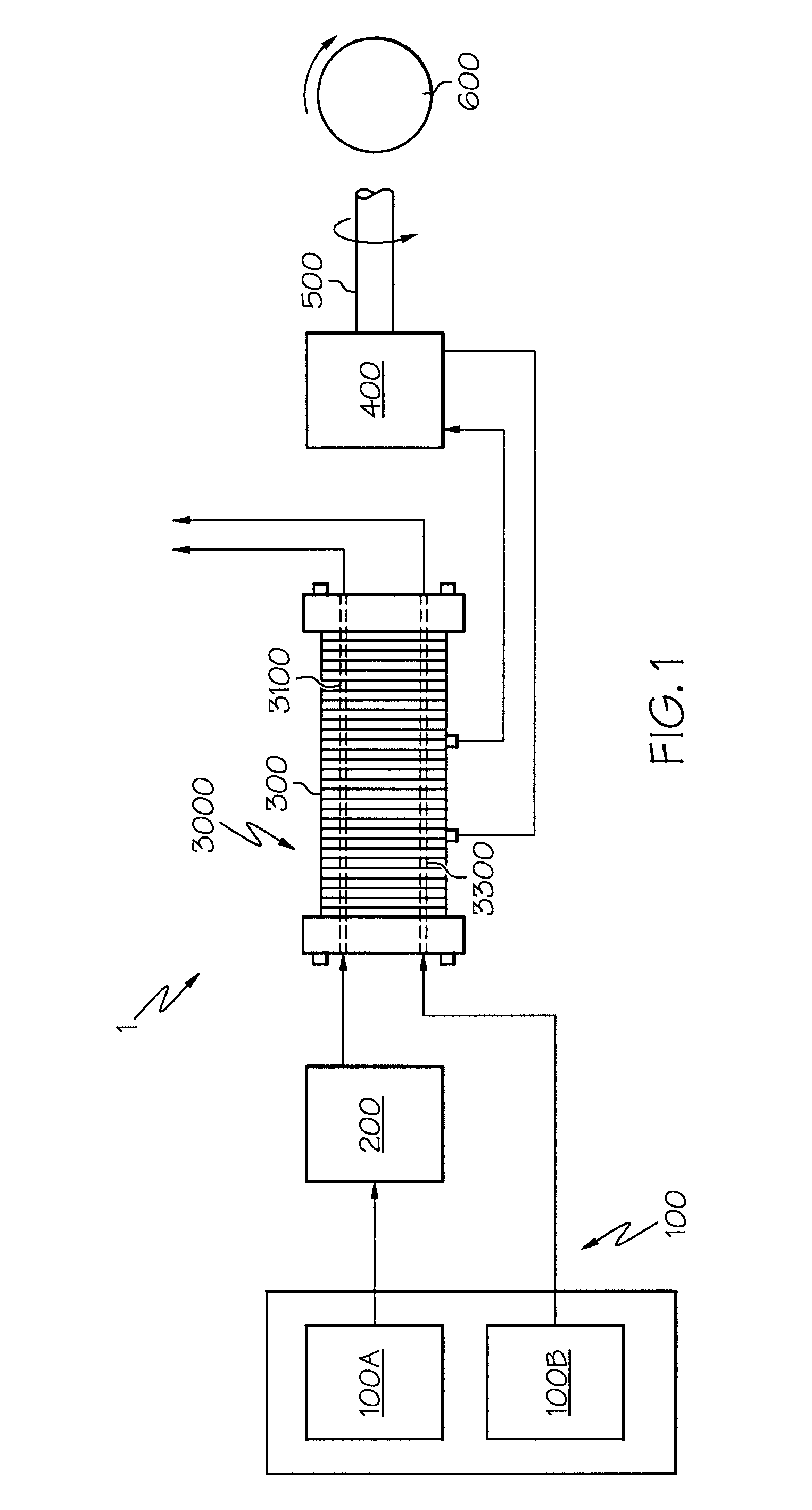
[0024]Referring initially to FIGS. 1 and 6, a block diagram highlights the major components of a mobile fuel cell system 1 according to the present invention (FIG. 1), as well as a representative placement of a fuel cell system into an automotive application (FIG. 6). Referring with particularity to FIG. 1, the system 1 includes a reactant delivery system 100 made up of fuel source 100A and oxygen source 100B, fuel processing system 200, stack 3000 containing multiple fuel cells 300, one or more optional energy storage devices 400, a drivetrain 500 and one or more motive devices 600, shown notionally as a wheel. One or both of the fuel or oxygen sources 100A, 100B may be supplied via tank or related container, and may optionally be pressurized by a compressor or related pump. While the present system 1 is shown for mobile (such as vehicular) applications, it will be appreciated by those skilled in the art that the use of the stack 3000 and its ancillary equipment is equally applicab...


PUM

PropertyMeasurementUnit
molar gas constantaaaaaaaaaa
voltageaaaaaaaaaa
concentrationaaaaaaaaaa

Abstract

A device and method to predict and regulate nitrogen concentration in a flow shifting system. In one aspect of the system, a bleed valve fluidly coupled to multiple fuel cell stacks is used to reduce the presence of nitrogen in an anode flowpath. One or more sensors can be used to measure voltage within one or both of the fuel cell stacks. By assessing fuel cell voltage changes within the anode flowpath and equating such changes with nitrogen fraction buildup, the system can manipulate the bleed valve at appropriate times to improve system operability. In one form of equating the sensed voltage changes with the nitrogen fraction buildup, a predictive algorithm can be used by a logic device in a controller to compare the sensed voltage so that the controller instructs the bleed valve when to open and close. In a variation, the controller can compare the sensed voltages against stored data rather than rely on a formula or related algorithm.

Description

BACKGROUND OF THE INVENTION[0001]The present invention relates generally to identifying and regulating the concentration of nitrogen buildup in an operating fuel cell, particularly to controlling the bleed of nitrogen in an anode loop of a flow shifting fuel cell system, and more particularly to simplifying a bleed algorithm for a flow shifting anode flowpath to maximize stable average stack voltages while minimizing hydrogen loss during the nitrogen bleed.[0002]In a typical fuel cell system, hydrogen or a hydrogen-rich gas is supplied through a flowpath to the anode side of a fuel cell while oxygen (such as in the form of atmospheric oxygen) is supplied through a separate flowpath to the cathode side of the fuel cell. In one form of fuel cell, called the proton exchange membrane (PEM) fuel cell, an electrolyte in the form of a membrane is sandwiched between the anode and cathode to produce a layered structure commonly referred to as a membrane electrode assembly (MEA). Each MEA for...

Claims


Application Information

Patent Timeline
Patent Type & Authority Applications(United States)
IPC IPC(8): H01M8/04
CPCH01M8/04231H01M8/04559H01M8/04761Y02E60/50H01M2008/1095H01M2250/20Y02T90/32H01M8/249Y02T90/40H01M8/04089
Inventor LIENKAMP, SEBASTIANWILLIMOWSKI, PETERARTHUR, DAVID A.
Owner GM GLOBAL TECH OPERATIONS LLC
Why Eureka
Try Eureka