Design structure for data communications systems

a data communication system and design structure technology, applied in the field of data communication system design structure, can solve the problems of excessive cross talk between channels, inability to accept data for one or more of a variety, excessive noise in received signals, etc., and achieve the effect of improving the accuracy of the signal detector and gaining the ag

Inactive Publication Date: 2008-06-19
IBM CORP
View PDF7 Cites 11 Cited by
  • Summary
  • Abstract
  • Description
  • Claims
  • Application Information

AI Technical Summary

Benefits of technology

[0020]In a particularly preferred embodiment of the present invention, there is provided a design structure of a receiver for a data communications system, the receiver comprising: a data path having an AGC loop receiving an input signal from a communication channel; and a signal detector receiving the input signal in parallel to the data path. In operation, the signal detector detects any loss of the input signal. The AGC is not directly involved in that detection. However, gain information from the AGC is employed to determine and control switching thresholds of the signal detector by varying the gain of a VGA within the signal detector. In particularly preferred embodiments of the present invention, the circuitry of the AGC and the VGA in the signal detector are made at least similar and preferably identical in order that they track each other well. In operation, the AGC sets its output at a known level. If the input signal to the AGC is also known, the gain of the AGC can then be determined. The AGC gain thus determined is then used to control the gain in, and therefore the switching thresholds of the signal detector. The accuracy of the signal detector is thereby improved. In another preferred embodiment of the present invention, the function of the VGA in the signal detector is integrated with the AGC in the data path in the interests of simplicity.

Problems solved by technology

In such a situation, the received data may not be valid for one or more of a variety of reasons, including, without limitation, excessive noise in the received signal, excessive cross talk between channels, and signal loss in the channel.
It is increasingly difficult to integrate this functionality into receiver designs as performance increases and available silicon area reduces.
As performance increases, the power consumption, and area of the amplifier also tends to increase.

Method used


Image

  • Design structure for data communications systems
  • Design structure for data communications systems
  • Design structure for data communications systems

Examples


Embodiment Construction

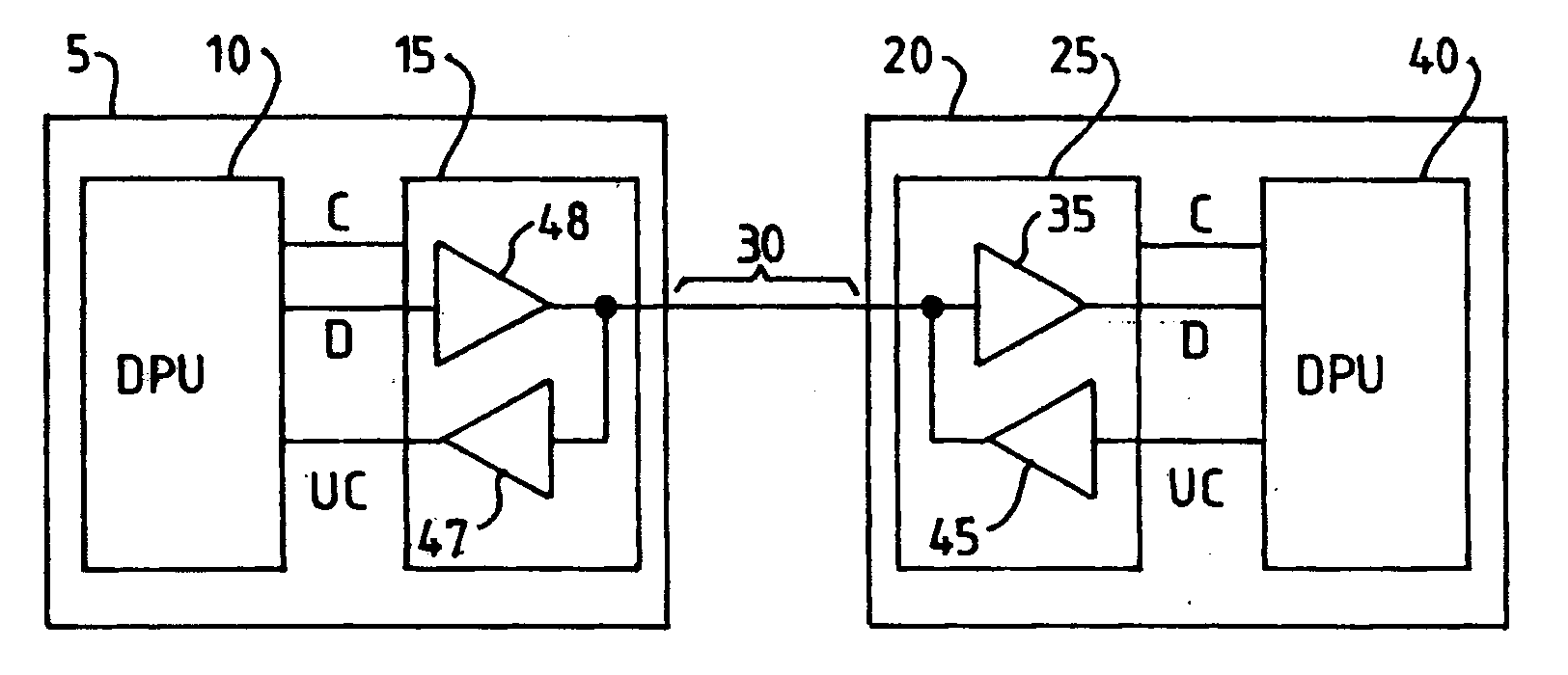
[0030]Referring to FIG. 1, a data communication system comprises a first data processing node 5 connected to a second data processing node 20 via a communication channel 30. The channel 30 may be wired or wireless. The first node 5 comprises a first data processing unit (DPU) 10 connected to a transmitter 15. The output of the transmitter 15 is connected to the channel 30. The transmitter 15 comprises a data path 48 for supplying serial input data D from the first DPU 10 to the channel 30. Likewise, the receiver 25 comprises a data path 35 for supplying data D received from the channel 30 the second DPU 40. The first DPU 10 and the second DPU 40 may be server computer systems, for example.

[0031]In operation, the data D is serially communicated between the first node 5 and second node 20 via the channel 30. The first node 5 and the second node 20 each typically comprise a serializer-deserializer (SERDES). In operation, the SERDES in the first node 5 converts parallel data words into ...


PUM


Abstract

A machine-readable medium thereupon stored a design structure; the design structure includes a receiver for a data communications system. The receiver includes a data path for receiving a data signal from a data channel, the data path comprising an automatic gain control (AGC) loop; and, a signal detector for generating a data valid signal indicative of the validity of the data signal in response to detection of the data signal on the channel exceeding a threshold and in dependence upon gain information from the AGC loop in the data path.

Description

CROSS-REFERENCE TO RELATED APPLICATIONS[0001]The present application is a Continuation-In-Part (CIP) application of U.S. patent application Ser. No. 11 / 737,319 filed Apr. 19, 2007 with the United States Patent and Trademark Office, which claims the benefit of priority of United Kingdom Patent Application No. 0611508.3 filed Jun. 10, 2006 with the United Kingdom Patent Office. The content of both applications are incorporated herein by reference in their entireties.FIELD OF THE INVENTION[0002]The present invention generally relates a design structure of data communications systems and in particularly to a design structure of receivers for data communications systems.BACKGROUND OF THE INVENTION[0003]A conventional data communication system comprises a first and a second node interconnected by an intervening serial data communication channel, such as a wire link or optical fiber link. The first node typically comprises a first data processing unit (DPU) connected to a transmitter. The ...

Claims


Application Information

Patent Timeline
Patent Type & Authority Applications(United States)
IPC IPC(8): H04B1/06
CPCH04L25/063H04L25/0292
Inventor MASON, JAMESHSU, LOUISMURFET, PHIL J.NICHOLLS, GARETH J.
Owner IBM CORP
Why Eureka
Try Eureka