Method and apparatus to achieve more level thermal gradient

Active Publication Date: 2008-06-19
ADVANCED MICRO DEVICES INC
View PDF10 Cites 4 Cited by
  • Summary
  • Abstract
  • Description
  • Claims
  • Application Information

AI Technical Summary

Benefits of technology

[0010]One aspect of this invention is directed to achieving better uniformity of temperature while performing burn-in on the semiconductor device. One way to achieve better temperature uniformity is to increase activity in the cache(s) during burn-in by changing operation of the cache so that during burn-in a plurality of memory locations in the cache(s) are accessed simultaneously thereby increasing activity in the cache to achieve higher power utilization in the cache during burn-in as compared to normal operation of the semiconductor device, when, e.g., used in normal operation in a system. In an embodiment, that is accomplished by activating a plurality of ways simultaneously to increase activity in the cache. Another embodiment provides for accessing multiple cache lines in parallel during burn-in testing to increase activity in the cache.

Problems solved by technology

For semiconductor devices, it often takes time for a failure to manifest itself.
That is, although the semiconductor device may initially pass all tests, after a short time in the field the device fails.
By operating the device at an elevated temperature and / or voltage, the failure mechanism is accelerated and therefore occurs earlier in time.
At some higher temperature (dependent on package substrate and die size) the C4 bumps on the die start to crack from stress caused by thermal coefficients of expansion (TCE) mismatches in silicon and the package, as well as potentially shortening the overall life of the product.
At even higher temperature damage to the device itself can occur.
Thus, the window of desired and useful temperatures is relatively small.
Today's semiconductor devices, such as high power microprocessors, have a relatively new problem: a thermal gradient that prevents testing all areas of the die at the required temperature.
That is, the surface of the die is not at a uniform temperature.
Therefore, the manufacturing process makes trade-offs between taking longer to burn-in the die or exceeding desired temperature limits.
Thus, as semiconductor devices shrink from 130 nm to 90 nm, and then to 65 nm, and 45 nm, the thermal gradient problem will continue to increase.
Thus, the problem of thermal gradients is expected to continue to increase.
A second option is to ship semiconductor devices of reduced quality by not extending the burn-in times. Obviously, that approach is generally not acceptable.
A third option would be to increase the temperature to accelerate the cooler areas, but that could raise the temperature in higher power density areas beyond the safe limits and possibly create new problems in the silicon.

Method used


Image

  • Method and apparatus to achieve more level thermal gradient
  • Method and apparatus to achieve more level thermal gradient
  • Method and apparatus to achieve more level thermal gradient

Examples


Embodiment Construction

)

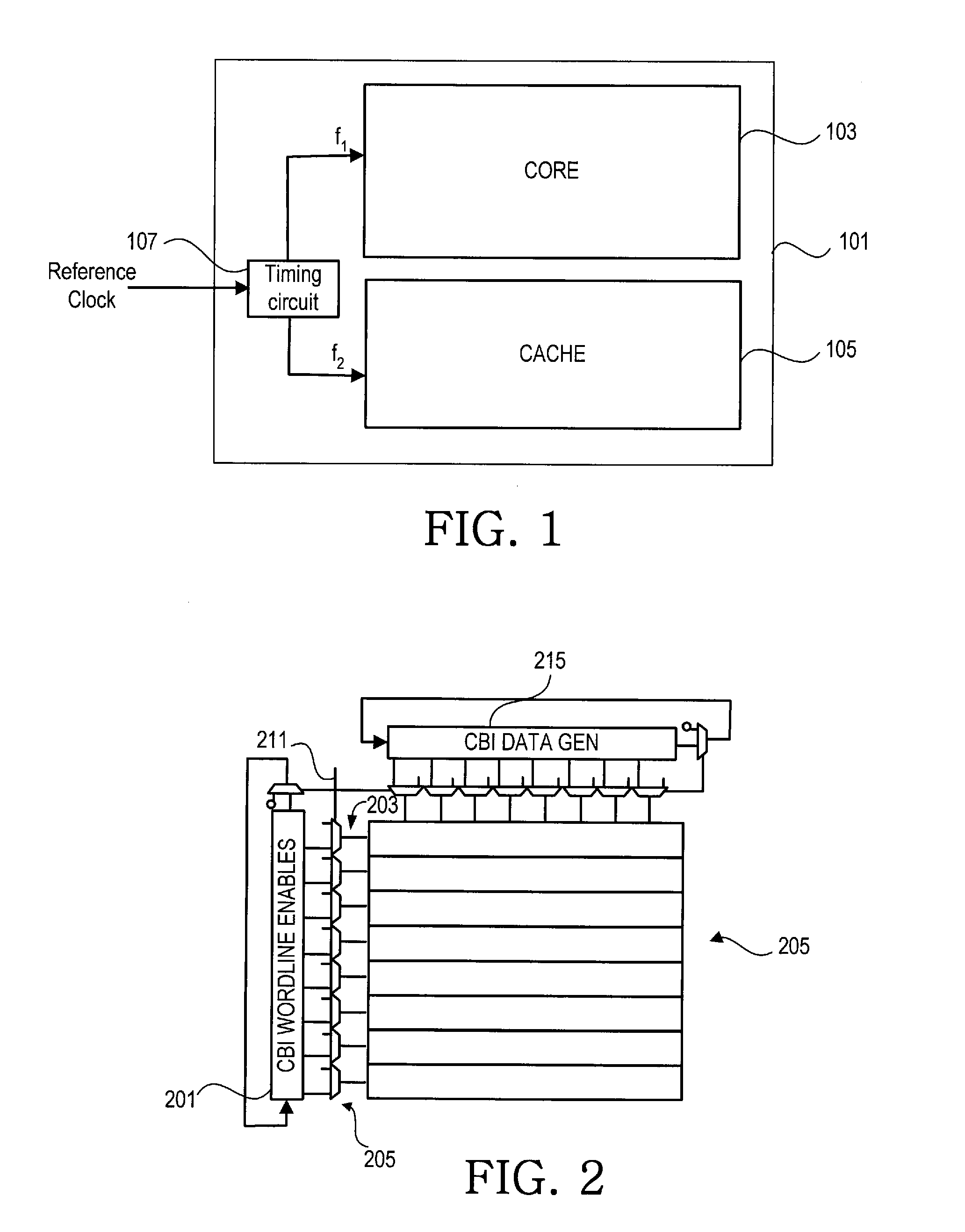
[0018]Referring to FIG. 1, a typical microprocessor 101 is shown. As shown in FIG. 1, microprocessors are divided into two major areas: the core region 103 and the cache 105. The “core” includes the central processing unit and can have a high number of transistors switching at any one time. The “cache” contains memory elements and typically has a low percentage of transistors active. Further, the core typically requires faster transistors which draw more power even in a static mode. The cache can use transistors with a much lower leakage value. Hence, the core will typically consume more power per area (higher power density) than the cache during normal operation and during burn-in unless steps are taken to address the different power density differences in the core and cache during burn-in. The different power consumption in the core and cache areas of the processor exacerbates burn-in problems due to thermal gradients. Note that cache 105 may include multiple caches, e.g., L1, L2...


PUM


Abstract

Achieving better uniformity of temperature on an integrated circuit while performing burn-in can result in reduced burn-in time and more uniform acceleration. One way to achieve better temperature uniformity is to control dynamic power in the core and cache by operating at different frequencies and increasing switching activity in the cache(s) during burn-in by changing operation of the cache so that during burn-in a plurality of memory locations in the cache(s) are accessed simultaneously, thereby increasing activity in the cache to achieve higher power utilization in the cache during burn-in.

Description

BACKGROUND[0001]1. Field of the Invention[0002]This invention relates to manufacturing of integrated circuits and more particularly to burn-in.[0003]2. Description of the Related Art[0004]For semiconductor devices, it often takes time for a failure to manifest itself. That is, although the semiconductor device may initially pass all tests, after a short time in the field the device fails. That is commonly referred to as infant mortality. In order to detect such latent defects, the manufacturing process typically employs an approach called burn-in to detect these latent failures. During burn-in the device is operated at elevated temperatures and / or voltages. By operating the device at an elevated temperature and / or voltage, the failure mechanism is accelerated and therefore occurs earlier in time. Tests performed after burn-in can determine whether latent defects uncovered during burn-in are present in the device. Burn-in time is typically measured in hours and is a function of tempe...

Claims


Application Information

Patent Timeline
IPC IPC(8): G06F12/08
CPCG06F12/0864G06F12/0846
Inventor BIENEK, MICHAEL D.ANDRADE, VICTOR F.POSEY, RANDAL L.BRAGANZA, MICHAEL C.
Owner ADVANCED MICRO DEVICES INC
Why Eureka
Try Eureka