Apparatus and Method for Improving Center Hole Radial Runout Control in Optical Disk Manufacturing

a technology of radial runout and apparatus, which is applied in the direction of mechanical control devices, process and machine control, instruments, etc., can solve the problems of large mismatches, increased complexity, and high cost of designing and modifying molds

Inactive Publication Date: 2008-06-26
TECHNICOLOR INC
View PDF10 Cites 4 Cited by
  • Summary
  • Abstract
  • Description
  • Claims
  • Application Information

AI Technical Summary

Benefits of technology

[0006]An apparatus for controlling radial runout between disk portions of an optical disk includes a cylindrical pin having at least two diameters. The pin is dimensioned and configured to permit disk portions having different cent

Problems solved by technology

Since these layers are typically polymeric, large mismatches can occur due to differences in the coefficients of expansion/contraction of the materials.
However, designing and modifying molds is costly and difficult.
The level of complexity is incre

Method used


Image

  • Apparatus and Method for Improving Center Hole Radial Runout Control in Optical Disk Manufacturing
  • Apparatus and Method for Improving Center Hole Radial Runout Control in Optical Disk Manufacturing
  • Apparatus and Method for Improving Center Hole Radial Runout Control in Optical Disk Manufacturing

Examples


Embodiment Construction

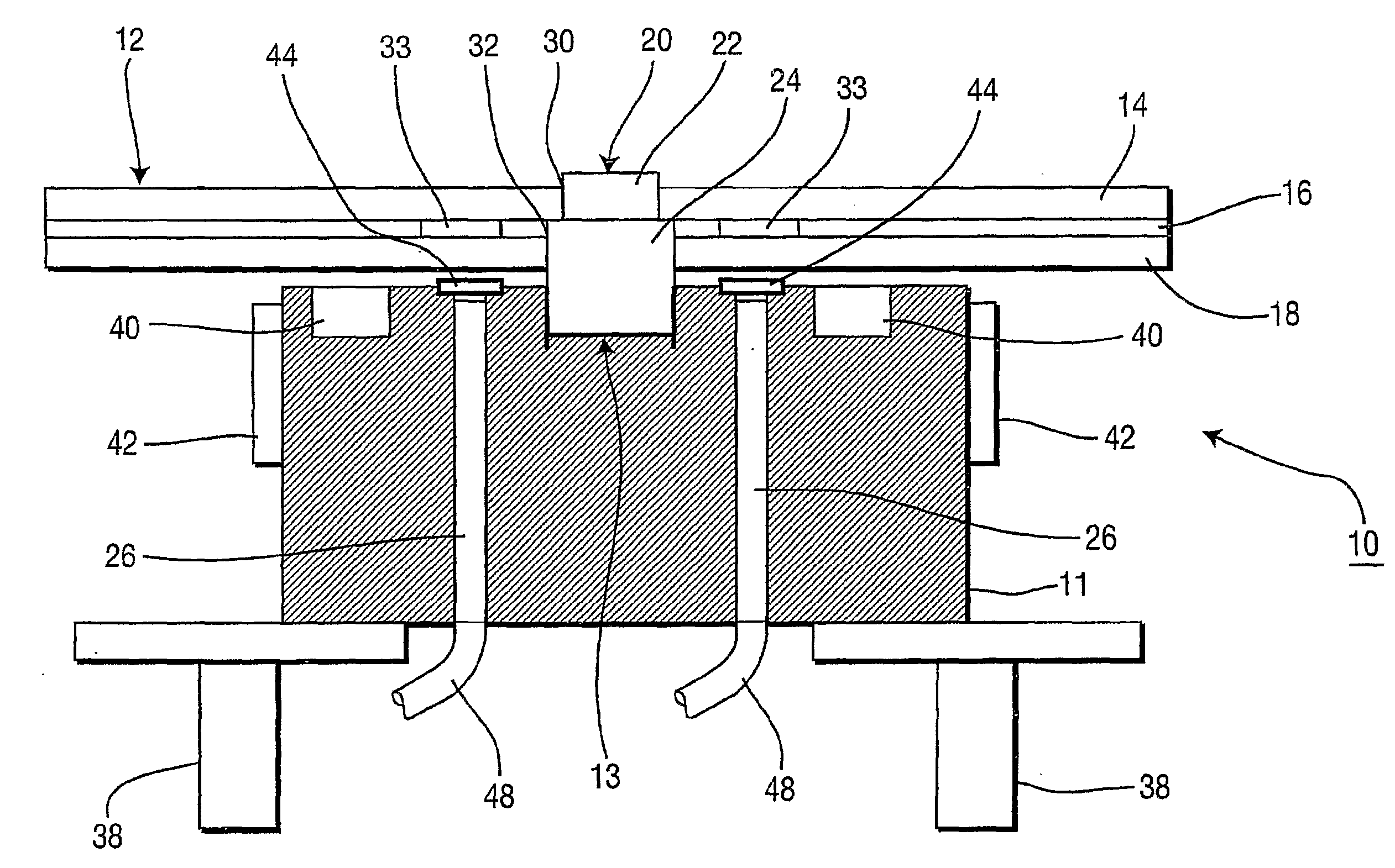
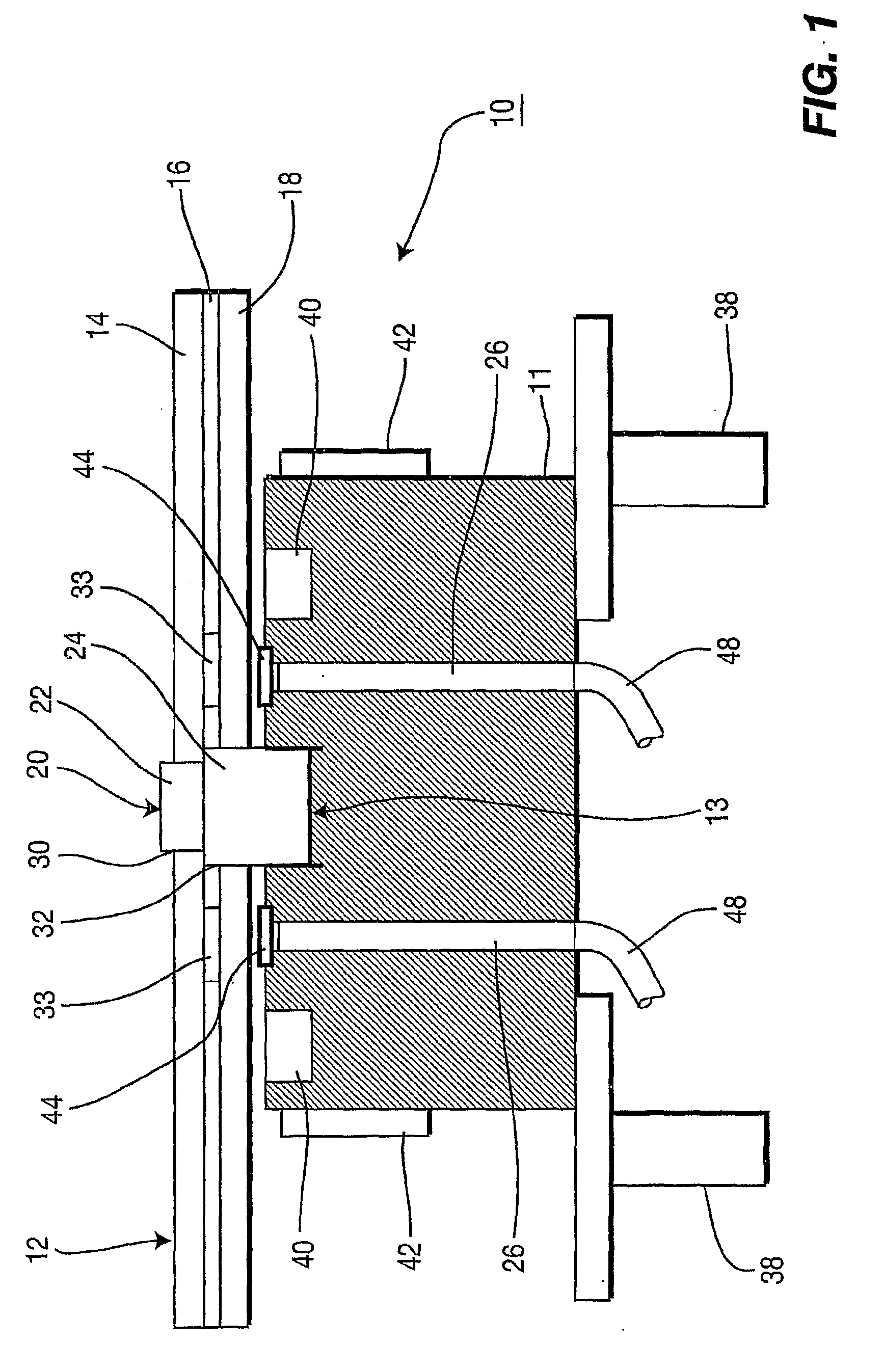
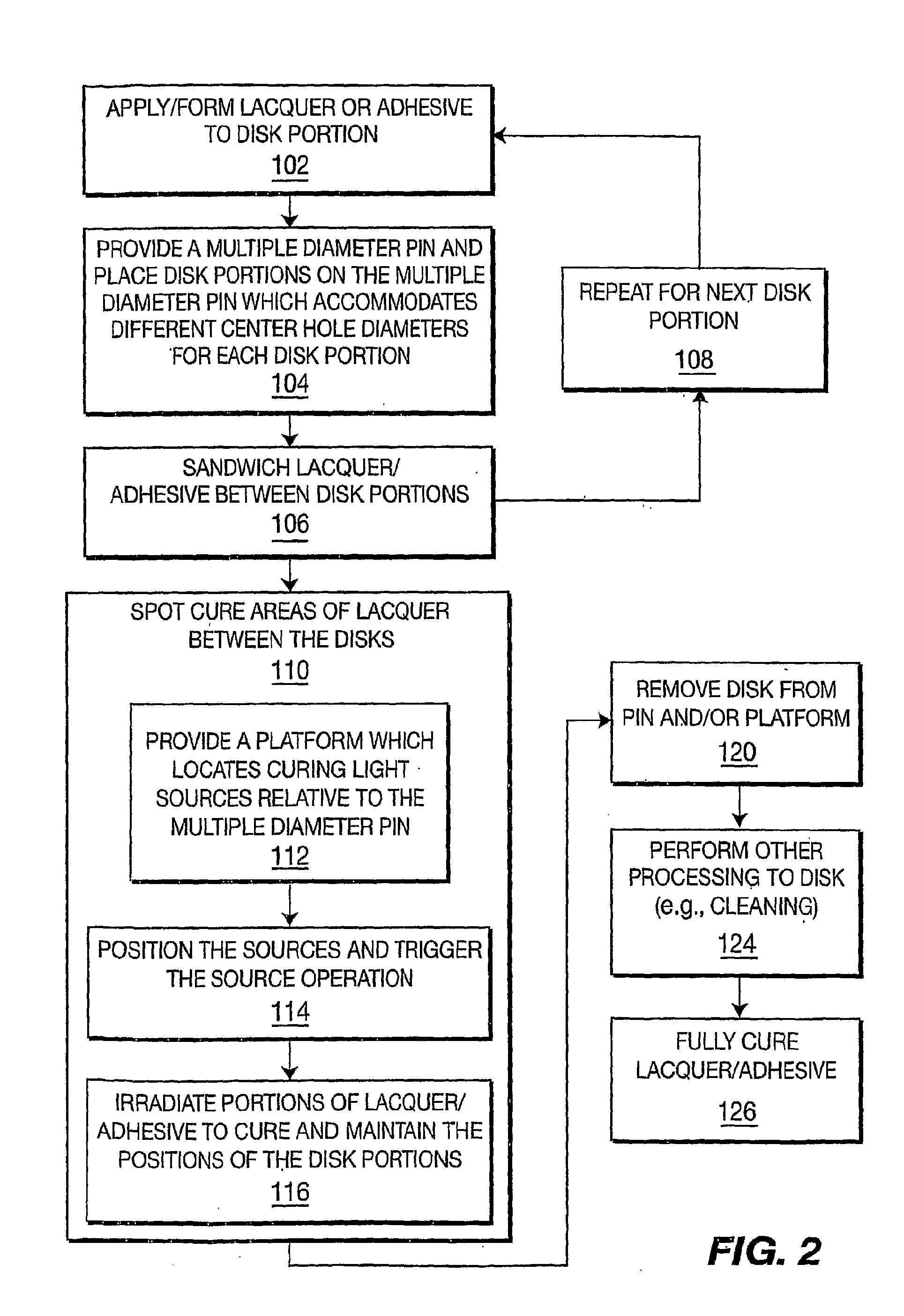
[0012]The present invention provides a method and apparatus for controlling radial runout between disk portions (e.g., layers, substrates or halves) in the manufacture of optical disks. In one particularly useful embodiment, an apparatus includes a multiple diameter pin. The pin includes two or more different diameters, each diameter dimensioned to accommodate a center hole of a particular type of disk portion (or half). The center hole may vary between disk portions as a result of different materials with different thermal characteristics or other reasons. The pin may be part of a fixture, which includes a spot-curing device. The spot-curing device may include predetermined locations where a curable material is placed between the disk portions so as to provide a quick cure of an adhesive to bond the disks either permanently or temporarily. In this way, the disk positions are maintained, aligned and the disk is movable to permit a full cure without the worry of misalignment.

[0013]It...


PUM

PropertyMeasurementUnit
Diameteraaaaaaaaaa
Distanceaaaaaaaaaa
Lightaaaaaaaaaa

Abstract

An apparatus and method for controlling radial runout between stacked disk portions (14, 18) and providing a cylindrical pin (20) having at least two diameters (22, 24). The pin is dimensioned and configured to permit the disk portions, which have different center hole dimensions, to be indexed such that a center hole of each disk portion is received by a separate diameter of the pin. The disk portions are maintained in spatial relationship as provided by the pin by spot curing a portion of the adhesive.

Description

FIELD OF THE INVENTION[0001]The present invention generally relates to manufacturing optical disks such as compact disks (CDs) and digital video disks (DVDs) and, more particularly, to an apparatus and method for controlling radial runout between constituent disk layers of an optical disk.BACKGROUND OF THE INVENTION[0002]Digital disks such as compact disks (CDs) or digital versatile disks (DVDs) may include a multiple layer process for manufacture. The disk may include a first layer having a pattern of microscopic pits or readout information applied thereto. The pattern of pits includes the digital readout information for the disk. The layer may have one or more additional layers applied to it. The readout surface may include a single or dual-layer readout surface that may include a sputtered-on reflective (e.g., aluminum) layer. These one or more additional layers may be bonded to the first layer or subsequent layers to form a completed optical disk.[0003]Each layer may include a d...

Claims


Application Information

Patent Timeline
IPC IPC(8): B29C65/54
CPCB29C65/02B29C65/7808B29C65/7855B29C66/21B29C66/452B29L2017/005Y10T156/17G11B7/26B29C65/48B29C65/4835B29C65/4845B29C65/00B29C65/14B29C65/1412B29C65/1406B29C66/71B29C66/72321B29C66/1122B29C66/73132B29K2069/00
Inventor SANOCKI, DANIEL JAYHAMERSLEY, ALAN BRUCELUCAS, WILLIAM GARRICK
Owner TECHNICOLOR INC
Why Eureka
Try Eureka