Circuit controller, inrush current limiting circuit, inrush current limiting circuit with battery, inverter, and inverter with battery

Inactive Publication Date: 2008-06-26
PANASONIC EV ENERGY CO LTD
View PDF16 Cites 36 Cited by
  • Summary
  • Abstract
  • Description
  • Claims
  • Application Information

AI Technical Summary

Benefits of technology

[0071]In the inverter, the inrush current limiting circuit, and the circuit controller of the invention, the temperature of the limiting resistor is calculated based on an actual resistor inter-terminal voltage and resistor current after the start of energization with current supplied from the d.c. power source through the switching circuit and the limiting resistor. Since the temperature of the limiting resistor fluctuates in accordance with the resistance value of the limiting resistor, it can be calculated based on the resistance value of the limiting resistor corresponding to the resistor inter-terminal voltage and resistor current. Especially, the inverter of the invention can accurately calculate the temperature of the limiting resistor based on the actually measured resistor inter-terminal voltage and resistor current. That is, it can obtain a calculated temperature with a small deviation from the actual temperature of the limiting resistor.
[0072]In the inverter, the inrush current limiting circuit, and the circuit controller of the invention, the temperature-basis open circuit determining means determines whether or not the switching circuit is to be opened based on an accurately calculated temperature of the limiting resistor (with a small

Problems solved by technology

More specifically, if the voltage of the smoothing capacitor is lower than the output voltage of the filter circuit, it is determined that a failure such as short-circuit has occurred in the inverter or the smoothing capacitor and the current flowing in the limiting resistor is shut

Method used


Image

  • Circuit controller, inrush current limiting circuit, inrush current limiting circuit with battery, inverter, and inverter with battery
  • Circuit controller, inrush current limiting circuit, inrush current limiting circuit with battery, inverter, and inverter with battery
  • Circuit controller, inrush current limiting circuit, inrush current limiting circuit with battery, inverter, and inverter with battery

Examples


first embodiment

[0095]Referring now to the accompanying drawings, an inverter 21 will be described according to a first embodiment of the invention.

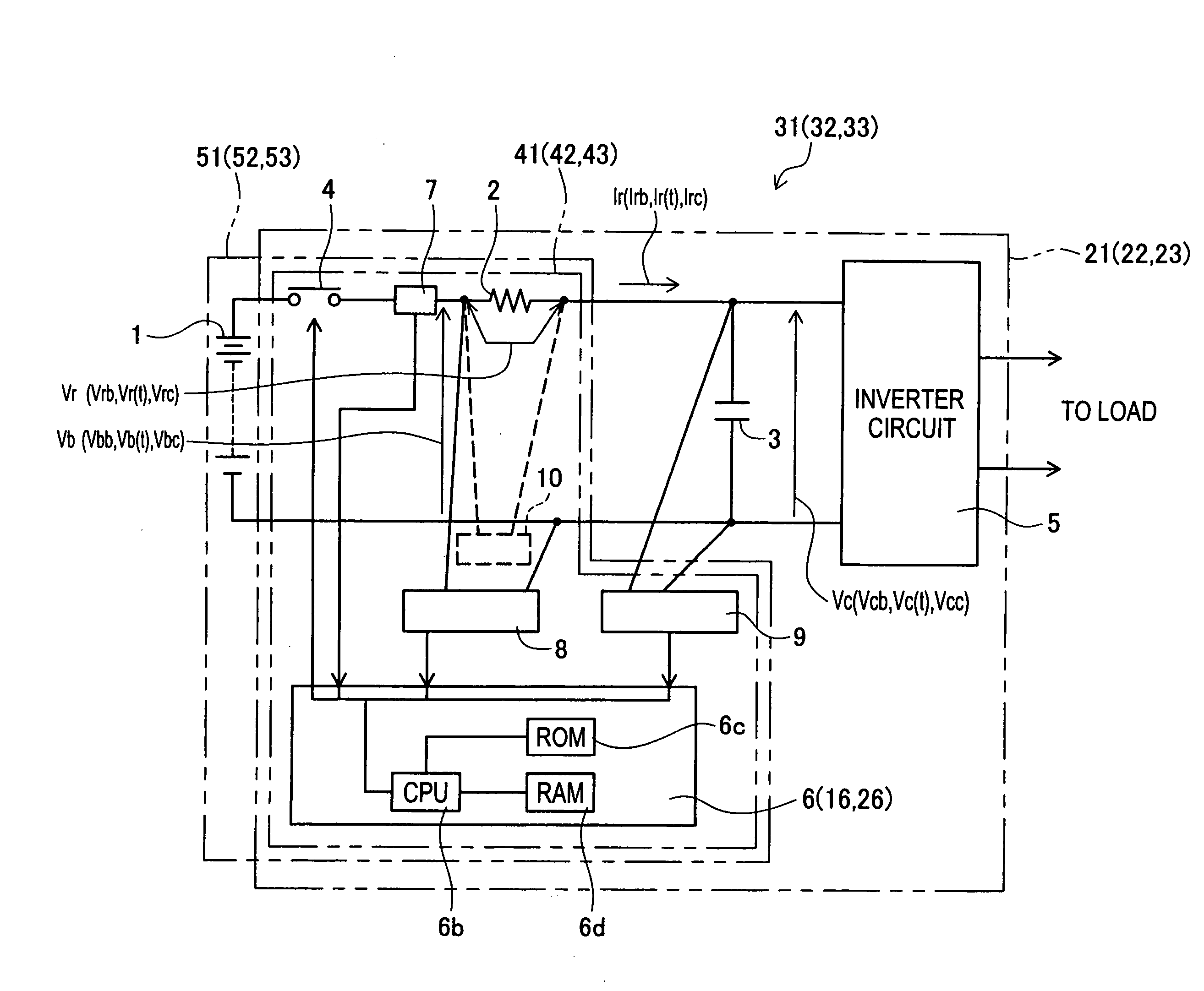
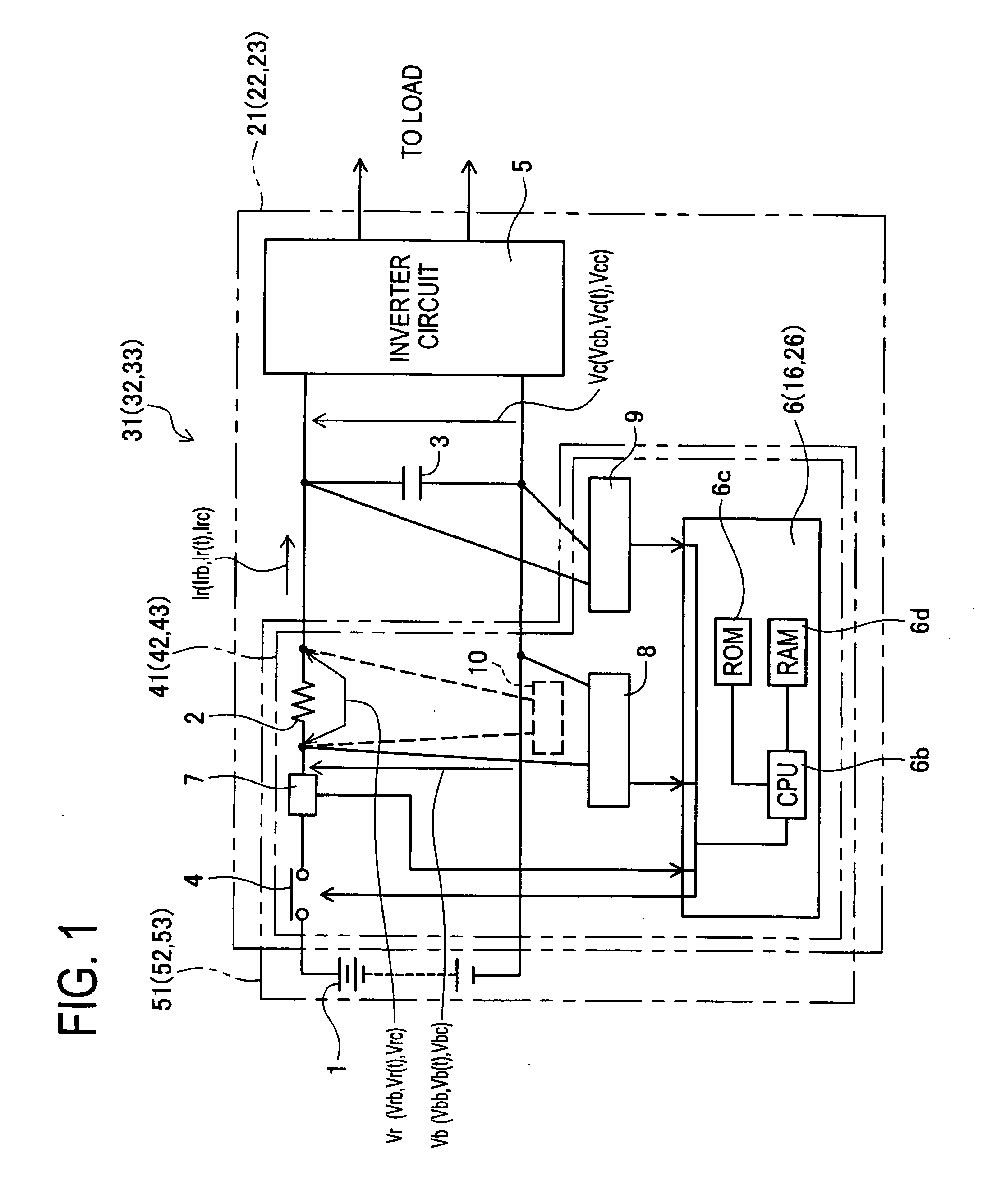
[0096]As illustrated in FIG. 1, the inverter 21 has an inverter circuit 5; a smoothing capacitor 3 that is closer to a battery (d.c. power source) 1 than the inverter circuit 5 is and connected to the inverter circuit 5 in parallel; and an inrush current limiting circuit 41 interposed between the battery 1 and the combination of the inverter circuit 5 and the smoothing capacitor 3.

[0097]The inrush current limiting circuit 41 has a limiting resistor 2 that is serially connected to the inverter circuit 5 and the smoothing capacitor 3, for limiting inrush current flowing from the battery 1 to the inverter circuit 5 and the smoothing capacitor 3; a switching circuit 4 for intermittently allowing a flow of resistor current Ir in the limiting resistor 2; and a current sensor 7 for measuring the resistor current Ir flowing in the limiting resistor 2. The inrus...

second embodiment

[0115]Next, an inverter 22 (inrush current limiting circuit 42) according to a second embodiment of the invention will be explained with reference to the drawings.

[0116]The inverter 22 (inrush current limiting circuit 42) of the second embodiment does not differ from the inverter 21 (inrush current limiting circuit 41) of the first embodiment except the ECU (circuit controller) for controlling the opening / closing of the switching circuit 4. Concretely, the ECU 16 of the second embodiment differs from the ECU 6 of the first embodiment in the processing performed with the stored program (see FIG. 1). Therefore, only the opening / closing control different from that of the first embodiment is explained herein and an explanation of other points will be skipped.

[0117]As illustrated in FIG. 1, the inverter 22 equipped with the battery 1 is defined as “inverter with battery 32”, and the inrush current limiting circuit 42 equipped with the battery 1 is defined as “inrush current limiting circ...

third embodiment

[0142]Next, an inverter 23 (inrush current limiting circuit 43) according to a third embodiment of the invention will be explained with reference to the drawings.

[0143]As seen from FIG. 1, the inverter 23 (inrush current limiting circuit 43) of the third embodiment does not differ from the inverter 21 (inrush current limiting circuit 41) of the first embodiment except the ECU (circuit controller) for controlling the opening / closing of the switching circuit 4. Concretely, the ECU 26 of the third embodiment differs from the ECU 6 of the first embodiment in the processing performed with the stored program. Therefore, only the opening / closing control different from that of the first embodiment is explained herein and an explanation of other points will be skipped.

[0144]As illustrated in FIG. 1, the inverter 23 equipped with the battery 1 is defined as “inverter with battery 33”, and the inrush current limiting circuit 43 equipped with the battery 1 is defined as “inrush current limiting...


PUM


Abstract

An inverter according to the invention includes an open circuit instructing device (ECU, Steps S5 to S8). The open circuit instructing device is for opening a switching circuit based on resistor inter-terminal voltage Vrb and resistor current Irb.

Description

BACKGROUND OF THE INVENTION[0001]1. Field of the Invention[0002]The present invention relates to a circuit controller for opening and closing a switching circuit that allows or disallows energization with current supplied from a d.c. power source through a limiting resistor. The invention also relates to an inrush current limiting circuit and an inverter that are equipped with such a circuit controller.[0003]2. Description of Related Art[0004]There have been proposed various circuit controllers for opening and closing a switching circuit that allows or disallows energization with current supplied from a d.c. power source through a limiting resistor. Also, various inrush current limiting circuits and inverters, which are each equipped with a circuit controller of the above type, have been proposed. (see e.g., Japanese Patent No. 3289743 and Japanese Patent No. 3269377).[0005]Japanese Patent No. 3289743 discloses a technique according to which a filter circuit, which has the same time...

Claims


Application Information

Patent Timeline
IPC IPC(8): G05F3/08
CPCH02M1/36H02H9/001
Inventor SUZUKI, MASAHIKOTOGASHI, KOUTAMIZOGUCHI, TETSUYAUEMURA, YUKIEKANAMARU, KUNIO
Owner PANASONIC EV ENERGY CO LTD
Why Eureka
Try Eureka