Supercharge Your Innovation With Domain-Expert AI Agents!

Direct modulation type voltage-controlled oscillator using mos varicap

Active Publication Date: 2008-06-26
PANASONIC CORP
View PDF3 Cites 4 Cited by
  • Summary
  • Abstract
  • Description
  • Claims
  • Application Information

AI Technical Summary

Benefits of technology

[0011]Therefore, an object of the present invention is to provide a direct modulation type voltage-controlled oscillator using a MOS varicap capable of optimally performing a modulation process by always using a peak gain without being influenced by component variations between MOS varicaps, a temperature change of the voltage-controlled oscillator and the like.
[0018]According to the present invention, even when a variable capacitor being composed of a MOS varicap is used, a capacitance value of the variable capacitor can be controlled in the vicinity of the center of the MOS varicap characteristic which varies linearly, thereby making it possible to always use a peak gain of the gain characteristic of the voltage-controlled oscillator.

Problems solved by technology

In the MOS varicap characteristic, however, there is a drawback that a range within which the capacity value of the MOS varicap linearly varies with respect to a change in a potential difference across the MOS varicap is narrower as compared to the PN varicap characteristic.
In the direct modulation type voltage-controlled oscillator using a variable capacitor as the MOS varicap, however, there is a drawback that an allowable range, of the potential difference across the MOS varicap, within which the peak gain can be obtained is narrower as compared to the direct modulation type voltage-controlled oscillator using a variable capacitor as the PN varicap.
However, the potential difference across the MOS varicap fluctuates due to component variations between the MOS varicaps, a temperature change of the voltage-controlled oscillator and the like.
Thus, there is a problem that it is difficult to optimally perform the modulation process by always using the peak gain.

Method used


Image

  • Direct modulation type voltage-controlled oscillator using mos varicap
  • Direct modulation type voltage-controlled oscillator using mos varicap
  • Direct modulation type voltage-controlled oscillator using mos varicap

Examples


first embodiment

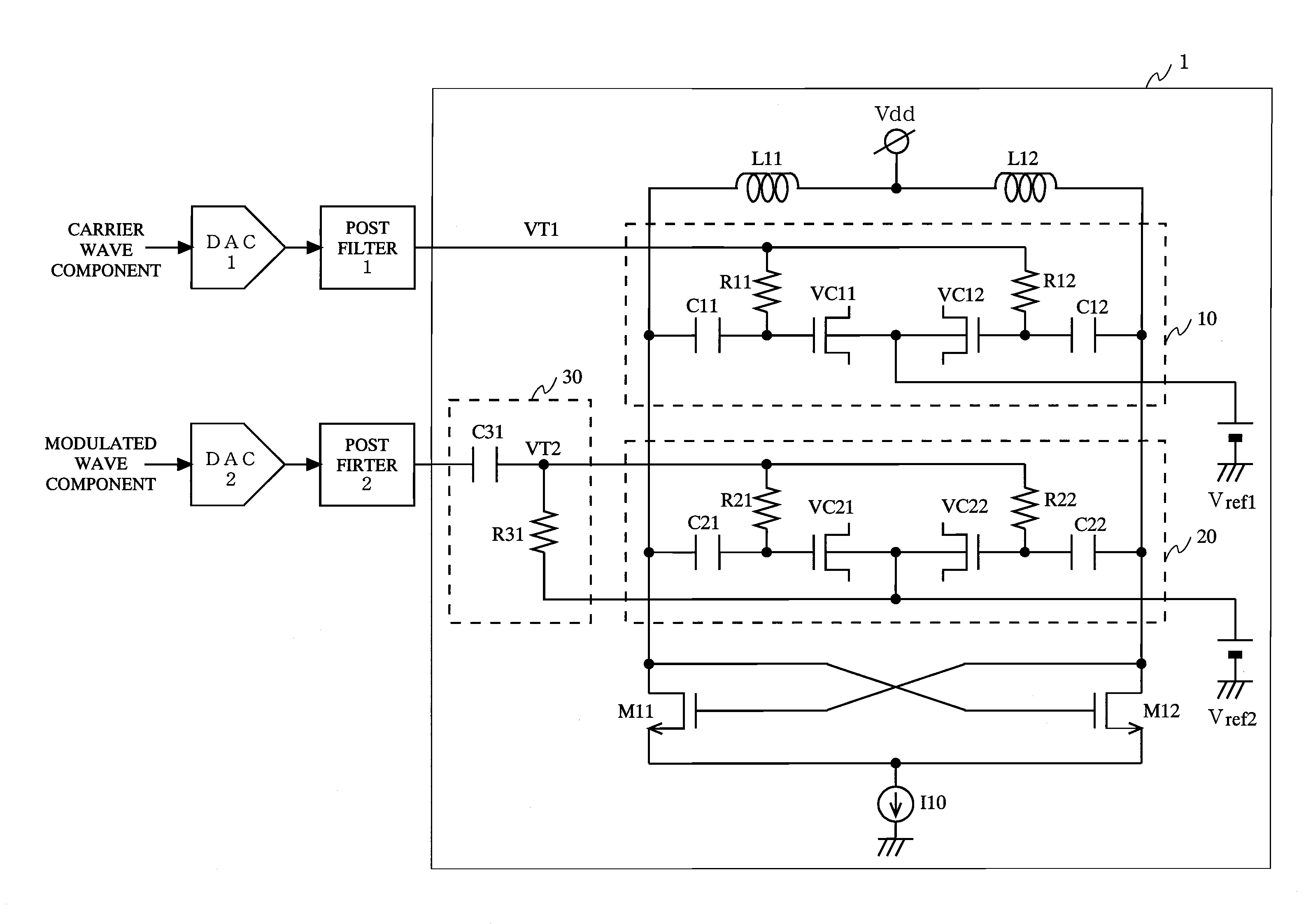
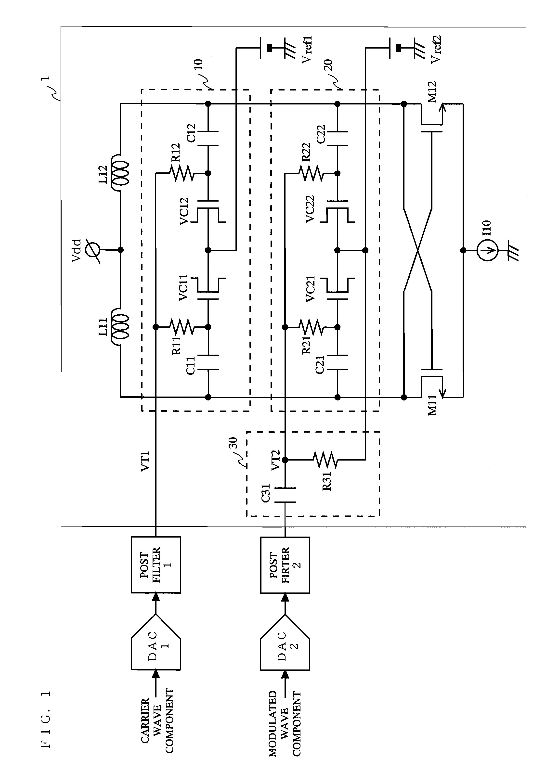
[0031]FIG. 1 is a circuit diagram illustrating a direct modulation type voltage-controlled oscillator 1 according to a first embodiment of the present invention. In FIG. 1, the direct modulation type voltage-controlled oscillator 1 according to the first embodiment comprises inductors L11 and L12, a first variable capacitor section 10 for a carrier wave component, a second variable capacitor section 20 for a modulated wave component, a DC control section 30, transistors M11 and M12, and a current source I10. To the first variable capacitor section 10, the carrier wave component is inputted via a DAC 1 and a post filter 1. To the second variable capacitor section 20, the modulated wave component is inputted via a DAC 2, a post filter 2 and the DC control section 30. The inductors L11 and L12 are connected in series with each other so as to form an inductor circuit. The transistors M11 and M12 are cross-coupled to each other so as to form a negative resistance circuit. The first and s...

second embodiment

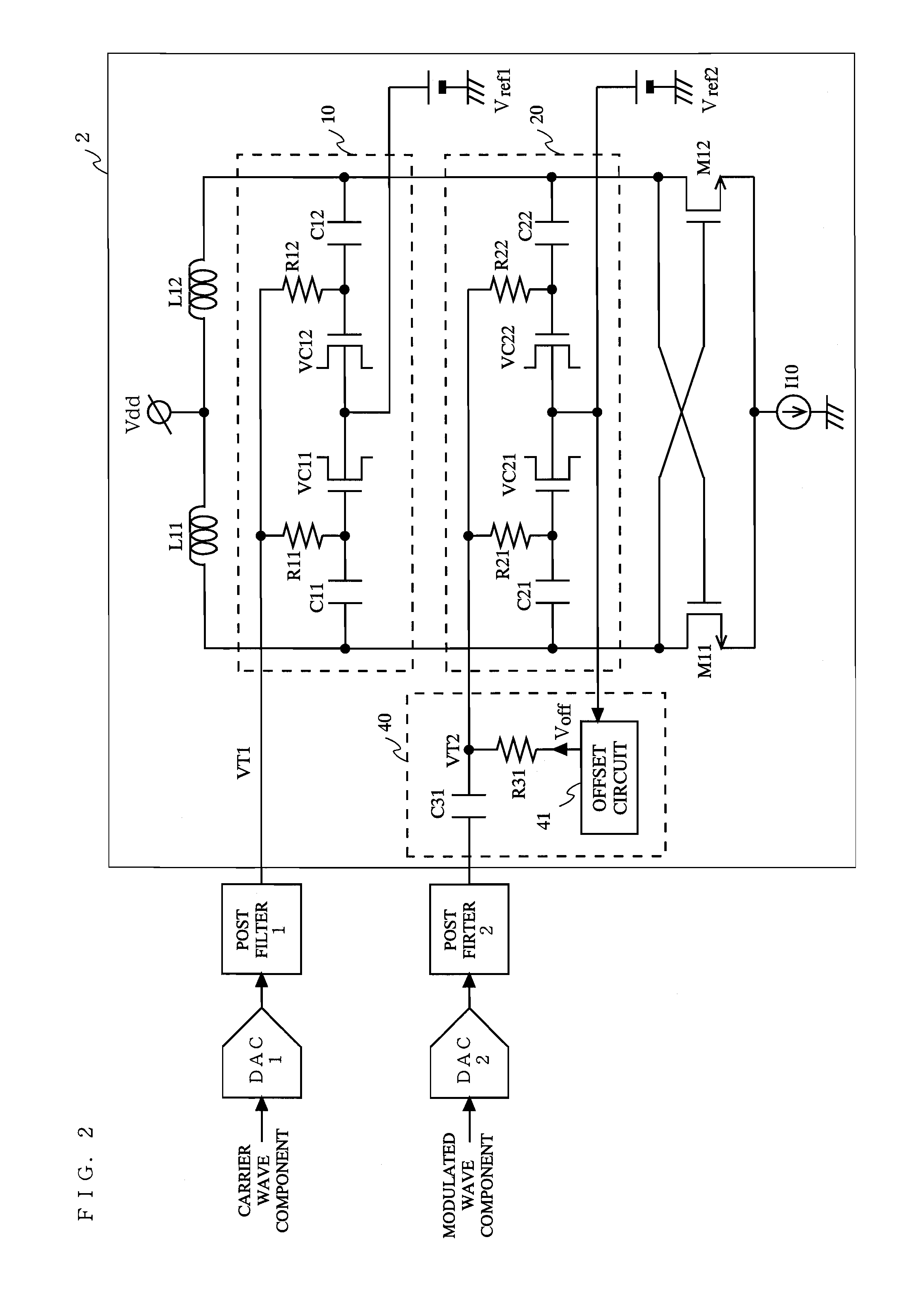
[0039]FIG. 2 is a circuit diagram of a direct modulation type voltage-controlled oscillator 2 according to a second embodiment of the present invention. In FIG. 2, the direct modulation type voltage-controlled oscillator 2 according to the second embodiment comprises the inductors L11 and L12, the first variable capacitor section 10 for the carrier wave component, the second variable capacitor section 20 for the modulated wave component, a DC control section 40, the transistors M11 and M12, and the current source I10. To the first variable capacitor section 10, the carrier wave component is inputted via the DAC 1 and the post filter 1. To the second variable capacitor section 20, the modulated wave component is inputted via the DAC 2, the post filter 2 and the DC control section 40. The direct modulation type voltage-controlled oscillator 2 is the same as the direct modulation type voltage-controlled oscillator 1 except that a configuration of the DC control section 40 included in t...

third embodiment

[0046]FIG. 4 is a circuit diagram of a direct modulation type voltage-controlled oscillator 3 according to a third embodiment of the present invention. In FIG. 4, the direct modulation type voltage-controlled oscillator 3 according to the third embodiment comprises the inductors L11 and L12, the first variable capacitor section 10 for the carrier wave component, the second variable capacitor section 20 for the modulated wave component, a DC control section 50, the transistors M11 and M12, and the current source I10. To the first variable capacitor section 10, the carrier wave component is inputted via the DAC 1 and the post filter 1. To the second variable capacitor section 20, the modulated wave component is inputted via the DAC 2, the post filter 2 and the DC control section 50. The direct modulation type voltage-controlled oscillator 3 is the same as the direct modulation type voltage-controlled oscillator 2 except that a configuration of the DC control section 50 included in the...


PUM


Abstract

Transistors M11 and M12 are cross-coupled to each other so as to form a negative resistance circuit. First and second variable capacitor sections 10 and 20 are connected in parallel with an inductor circuit so as to form a parallel resonant circuit. A first reference voltage Vref1 and a control voltage VT1 corresponding to a carrier wave component are fed to both terminals, respectively, of each of variable capacitors VC11 and VC12 included in the first variable capacitor section 10. A second reference voltage Vref2 and a control voltage VT2 corresponding to a modulated wave component are fed to both terminals, respectively, of each of variable capacitors VC21 and VC22 included in the second variable capacitor section 20. ADC control section 30 includes a resistance R31 interposed between the second reference voltage Vref2 and a common connection point of resistances R21 and R22, and a capacitor C31 for feeding only an AC component included in the modulated wave component to the common connection point of the resistances R21 and R22. Thus, a DC voltage, on which the AC component included in the modulated wave component is superimposed, is changed from a certain DC bias to a DC bias of the second reference voltage Vref2.

Description

BACKGROUND OF THE INVENTION[0001]1. Field of the Invention[0002]The present invention relates to a direct modulation type voltage-controlled oscillator using a MOS varicap, and more particularly to a voltage-controlled oscillator capable of performing a linear phase modulation.[0003]2. Description of the Background Art[0004]As is well known, a voltage-controlled oscillator (VCO) is widely used as a device for generating a local oscillation signal of a wireless communication device or the like. In particular, a direct modulation type voltage-controlled oscillator can perform a local oscillation process and a modulation process simultaneously. The direct modulation type voltage-controlled oscillator is disclosed in US Patent Publication No. 2005 / 0231296A1, for example.[0005]FIG. 8 is a diagram illustrating an exemplary configuration of a conventional direct modulation type voltage-controlled oscillator 100. The conventional direct modulation type voltage-controlled oscillator 100 comp...

Claims


Application Information

Patent Timeline
IPC IPC(8): H03B5/12
CPCH03C3/225H03B5/1253H03B5/1215H03B5/1228
Inventor MAEDA, MASAKATSU
Owner PANASONIC CORP
Features
  • R&D
  • Intellectual Property
  • Life Sciences
  • Materials
  • Tech Scout
  • Unparalleled Data Quality
  • Higher Quality Content
  • 60% Fewer Hallucinations
Learn More