

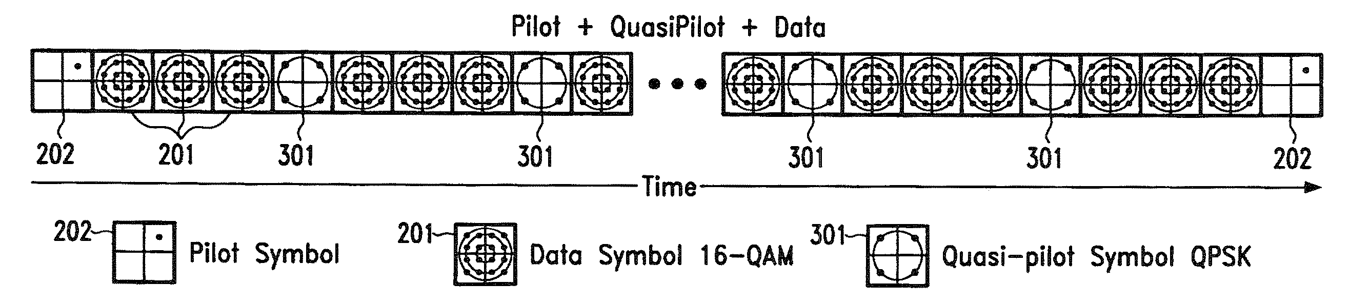
Quasi-Pilot Symbol Substitution
a substituted symbol and quadruple-pilot technology, applied in the field of data communication, can solve the problems of not only delay, but also errors in the received data after demodulation, and achieve the effect of improving the use of transmission capacity
- Summary
- Abstract
- Description
- Claims
- Application Information
AI Technical Summary
Benefits of technology
Problems solved by technology
Method used
Image

Examples
Embodiment Construction
[0039]The exemplary embodiments of the present invention will be described with reference to the figure drawings wherein like elements and structures are indicated by like reference numbers.
[0040]In the following the method according to the present invention is explained in terms of transmission of data in the time domain, that is positions of data symbols are positions in time, spacing is described as being distance in time and so on. However, the method can accordingly also be applied in the frequency domain with positions being carrier frequencies, spacing meaning frequency differences and so on. Likewise an extension into further data transmission domains or combinations of domains is easily possible, for example both in time and frequency as in an OFDM system.
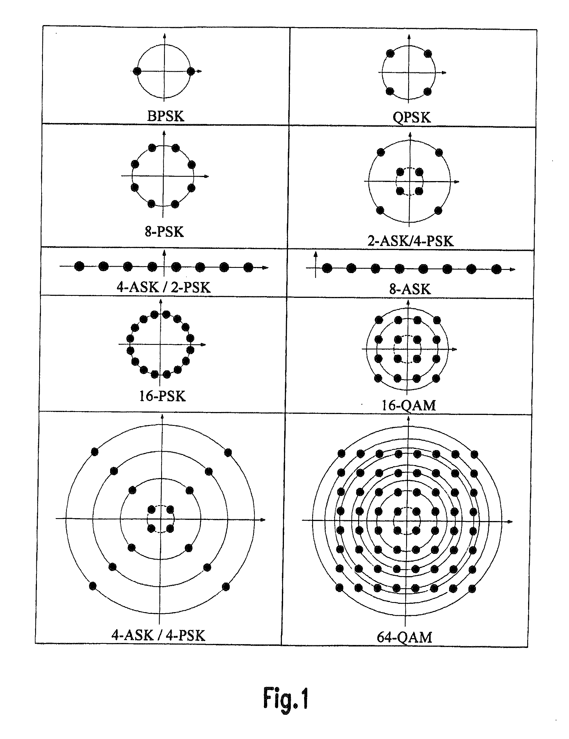
[0041]For simplicity, a data modulation scheme that exhibits a number of ambiguity levels that prohibit the efficient use of this symbol for channel estimation will be called herein below an HAM scheme (HAM=High Ambiguity ...
PUM
 Abstract
Description
Claims
Application Information