
Transmission Device, Transmission Power Control Method, and Radio Communication Device

a technology of transmission power and radio communication, which is applied in the direction of wireless communication, power management, sustainable buildings, etc., can solve the problem of not controlling the average output level of the transmitting signal, and achieve the effect of reducing the size reducing the power efficiency of the transmitting apparatus in the first mode, and reducing the period of use of the battery power supply mounted in the apparatus

Inactive Publication Date: 2008-06-26
PANASONIC CORP
View PDF9 Cites 5 Cited by
  • Summary
  • Abstract
  • Description
  • Claims
  • Application Information

AI Technical Summary

Benefits of technology

[0014]With this construction, in the first mode, for example, at the time of outputting high power, by operating the high-frequency power amplifier as a nonlinear amplifier, it is possible to increases power efficiency remarkably, and in the second mode, for example, at the time of outputting low power, by operating the high-frequency power amplifier as a linear amplifier, it is possible to control transmitting output power over a wide range and to use one amplifier extremely efficiently and to increase power efficiency remarkably.
[0018]With this construction, the input level of the high-frequency power amplifier is changed according to the average output power of the transmitting signal, so that it is possible to reduce leak power and to extend the control range of transmitting power by the power supply voltage when the high-frequency power amplifier operates as a nonlinear amplifier.
[0020]With this construction, the input level of the high-frequency power amplifier is changed according to the instantaneous output power of the transmitting signal, so that it is possible to follow an instantaneous change in the level and to reduce leak power and hence to improve the recurrence of an instantaneous change in the level.
[0022]With this construction, it is possible to enhance power efficiency remarkably in the first mode of operating the high-frequency power amplifier as a nonlinear amplifier and to control the transmitting output power over a wide range in the first mode and in second mode of operating the high-frequency power amplifier as a linear amplifier.
[0024]With this construction, the power efficiency of the transmitting apparatus in the first mode is high and hence the period of use of a battery power supply mounted in the apparatus can be elongated and the high-frequency power amplifier of the transmitting apparatus can be reduced in size, so that it is possible to make a more reduction in the size of the radio communication apparatus.
[0025]According to the transmitting apparatus, the method of controlling transmitting power, and the radio communication apparatus in accordance with the invention, it is possible to make power efficiency excellent and to extend the control range of transmitting output power.

Problems solved by technology

With this construction, in the second mode, the high-frequency power amplifier operates as a linear amplifier and hence its power supply voltage is constant and the high-frequency power amplifier can not amplitude modulate the transmitting signal and can not control the average output level of the transmitting signal.

Method used


Image

  • Transmission Device, Transmission Power Control Method, and Radio Communication Device
  • Transmission Device, Transmission Power Control Method, and Radio Communication Device
  • Transmission Device, Transmission Power Control Method, and Radio Communication Device

Examples


first embodiment

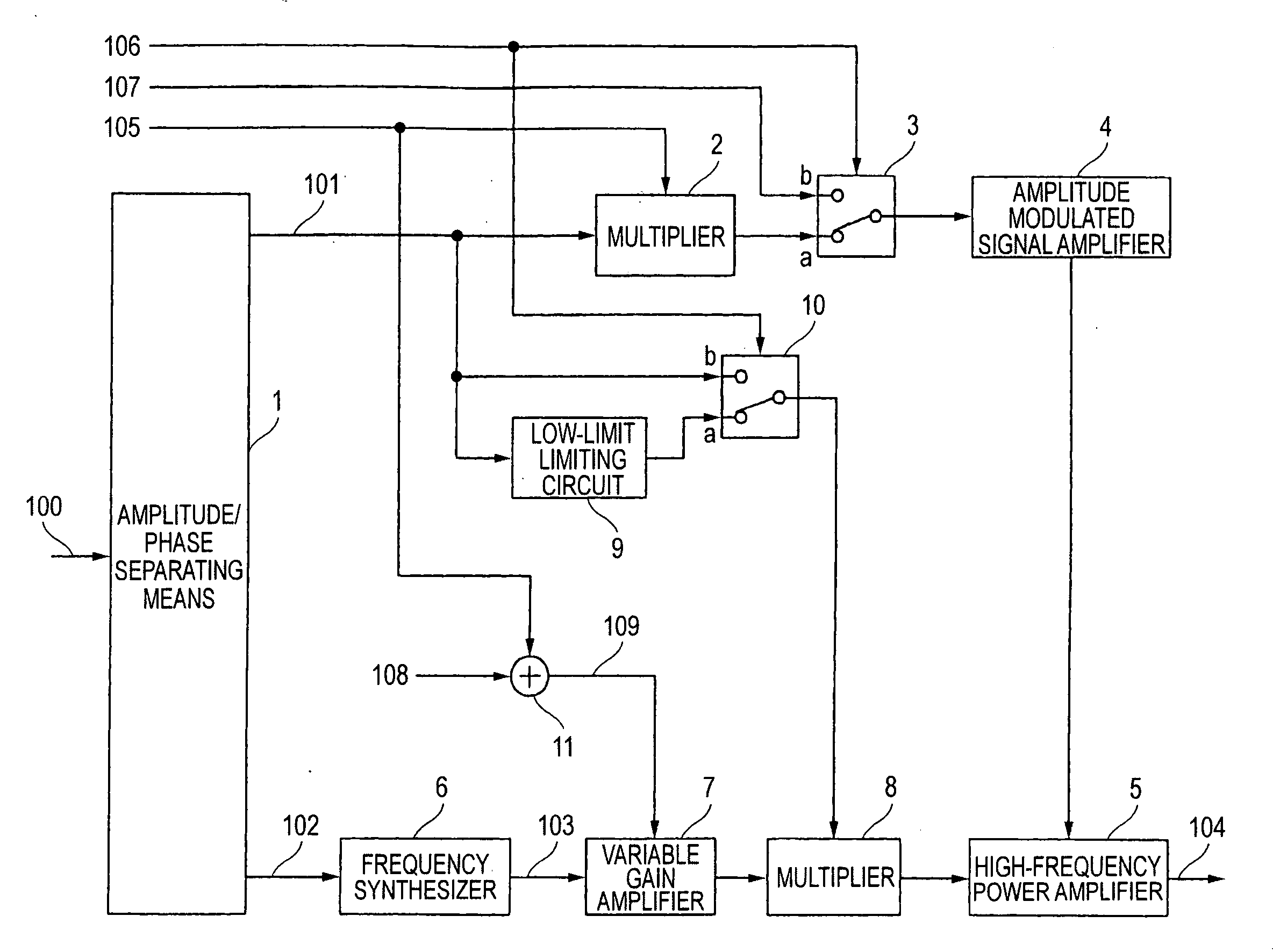
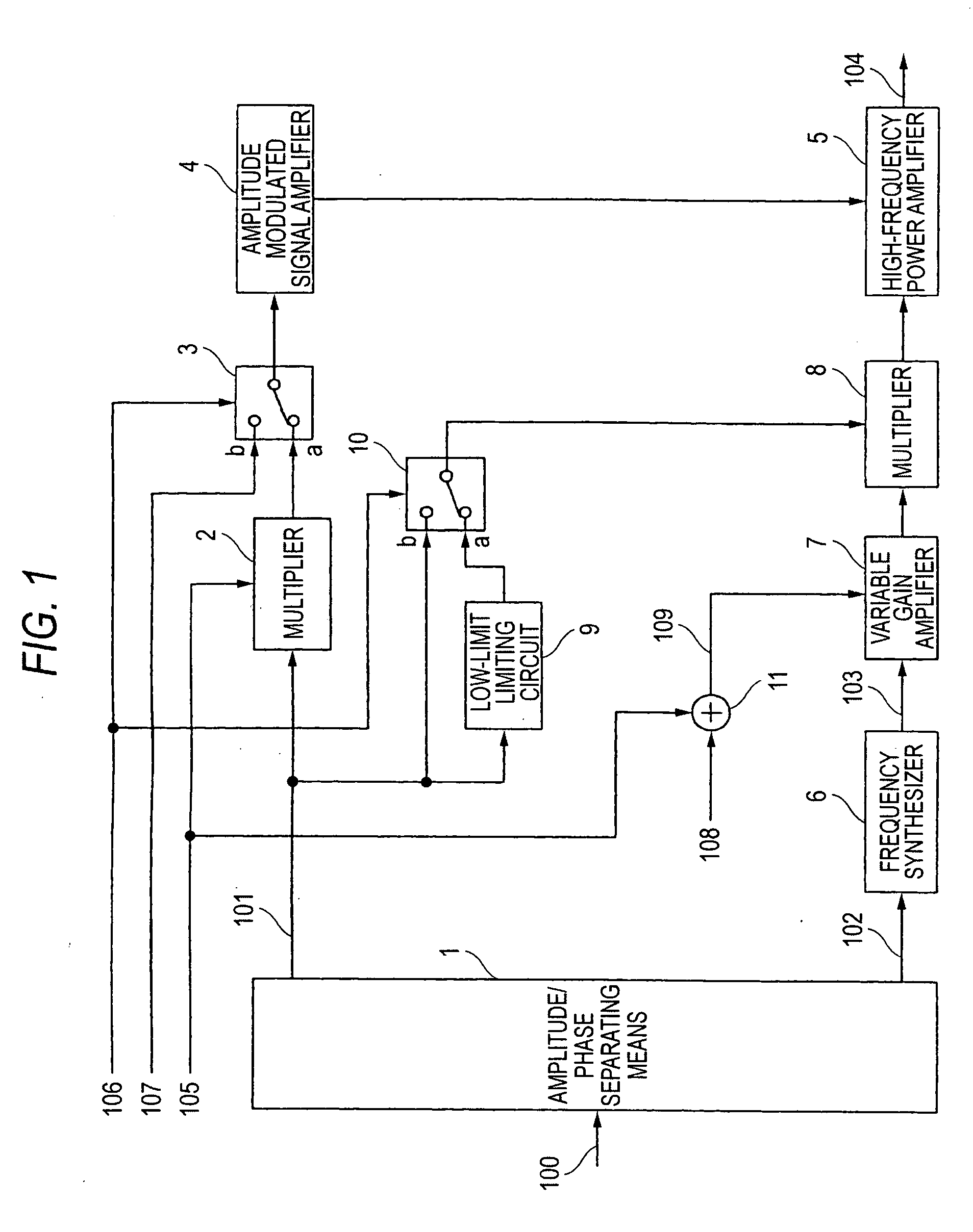
[0032]FIG. 1 is a block diagram showing the general construction of a transmitting apparatus so as to describe an embodiment of the invention. As shown in FIG. 1, the transmitting apparatus of this embodiment includes amplitude / phase separating means 1 that separates a base-band modulated signal 100 into a base band amplitude-modulated signal 101 and a base-band phase-modulated signal 102, a multiplier 2 that multiplies the base band amplitude-modulated signal 101 by a gain control signal 105, a switch 3 that is switched on the basis of a mode switching signal 106, an amplitude-modulated signal amplifier 4 that supplies a high-frequency power amplifier 5 with a power supply voltage, the high-frequency power amplifier 5 that amplifies the power of an input signal from a multiplier 8 and outputs a transmitting output signal 104, a frequency synthesizer 6 that phase modulates a carrier wave signal by the base-band phase-modulated signal 102 to produce a high-frequency phase-modulated s...


PUM


Abstract

The object of the present invention is to provide a transmitting apparatus and a transmitting power control method that can provide excellent power efficiency and a wide control range of transmitting output power, and a radio communication apparatus employing the transmitting apparatus.At the time of high output power, a high-frequency power amplifier (5) is operated as a nonlinear amplifier, whereby power efficiency when a transmitting signal is power-amplified can be enhanced. Further, at the time of low output power, the high-frequency power amplifier (5) is operated as a linear amplifier, whereby the control range of the transmitting output power can be extended. Still further, when the high-frequency power amplifier (5) is operated as a nonlinear amplifier, by varying the input level of the high-frequency power amplifier (5) according to the average output power of the transmitting signal by the variable gain amplifier (7), it is possible to reduce leak power and to extend the control range of the transmitting output power.

Description

TECHNICAL FIELD[0001]The present invention relates to a transmitting apparatus that power-amplifies a transmitting signal and a transmitting power controlling method, and a radio communication apparatus using this transmitting apparatus.BACKGROUND ART[0002]In a conventional high-frequency power amplifier for amplifying a modulated signal including an envelope variation component, an A-class or AB-class linear amplifier has been used to amplify the envelope variation component linearly. Such a linear amplifier is excellent in linearity but is inferior in power efficiency to a C-class or E-class non-linear amplifier because the linear amplifier always consumes power incident to a direct current bias component. For this reason, when such a high-frequency power amplifier is applied to a portable radio powered by a battery, there are brought about circumstances that the hours of use are shortened because the high-frequency power amplifier consumes large power. Moreover, when such high-fr...

Claims


Application Information

Patent Timeline
IPC IPC(8): H04B1/04H03F1/02H03G3/30H03F3/19H03F3/24H04B7/005
CPCH03F1/025Y02B60/50H04W52/52H03F3/19
Inventor ARAYASHIKI, MAMORUHARA, YOSHIHIROUDAGAWA, MASAHARU
Owner PANASONIC CORP
Learn More