Interbody fusion hybrid graft

a hybrid graft and interbody technology, applied in the field of surgical implants, can solve the problems of abnormal force applied to the cervical vertebra, bone material erosion, bone material erosion, etc., and achieve the effects of providing overall strength and durability to the structure, high force, and accelerating the healing process

Inactive Publication Date: 2008-06-26
MUSCULOSKELETAL TRANSPLANT FOUNDATIO
View PDF10 Cites 116 Cited by
  • Summary
  • Abstract
  • Description
  • Claims
  • Application Information

AI Technical Summary

Benefits of technology

[0026]It is another object of the invention to utilize a shaped cortical plastic implant block which provides the mechanical strength characteristics that can withstand compression forces and provide overall strength and durability to the structure.
[0027]It is still another object of the invention to provide a spinal fusion implant which uses a load bearing plastic component member to take up the high forces which can arise between two vertebral bodies and cortical cap members to accelerate the healing process.
[0028]It is yet another object of the invention to provide a pre-machined shaped allograft bone structure which can effectively promote new bone growth and accelerate healing.

Problems solved by technology

Injury or disease to the head, neck, or shoulders can cause abnormal forces to be applied on the cervical vertebra.
Metal plates screwed into the adjacent vertebrae work well, but after time post-operatively, the stress rise occurring at the screw position causes erosion of the bone and resultant slipping.
However, bone material and in particular cortical bone acceptable for use in implants is a scarce resource, being derived from limited number human tissue donor resources.
However, these long bones make up only a fraction of the available bone source.
The scarcity of desired donor bone makes it difficult to provide implants having the desired size and configuration for implantation between vertebrae, which can require relatively large implants.
The scarcity of suitable bone material has also hindered efforts to design and manufacture varying configurations of suitable implants for arthodesis of the spine.
Further, various implant configurations have not been physiologically possible to obtain given the structural and geometrical constraints of available donor bone.

Method used


Image

  • Interbody fusion hybrid graft
  • Interbody fusion hybrid graft
  • Interbody fusion hybrid graft

Examples


Embodiment Construction

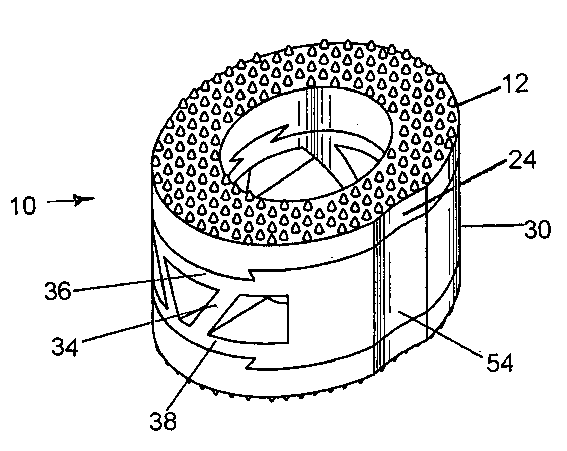
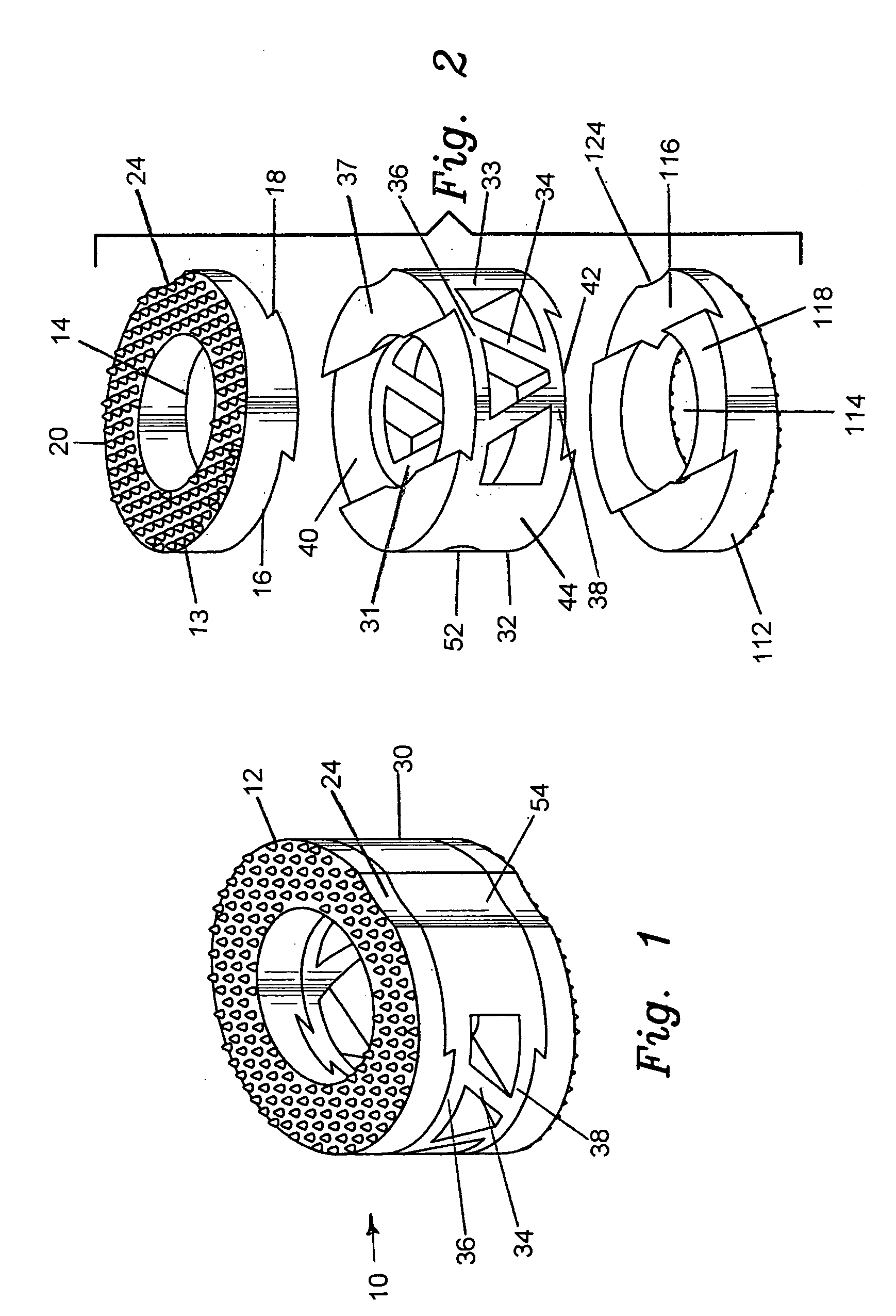
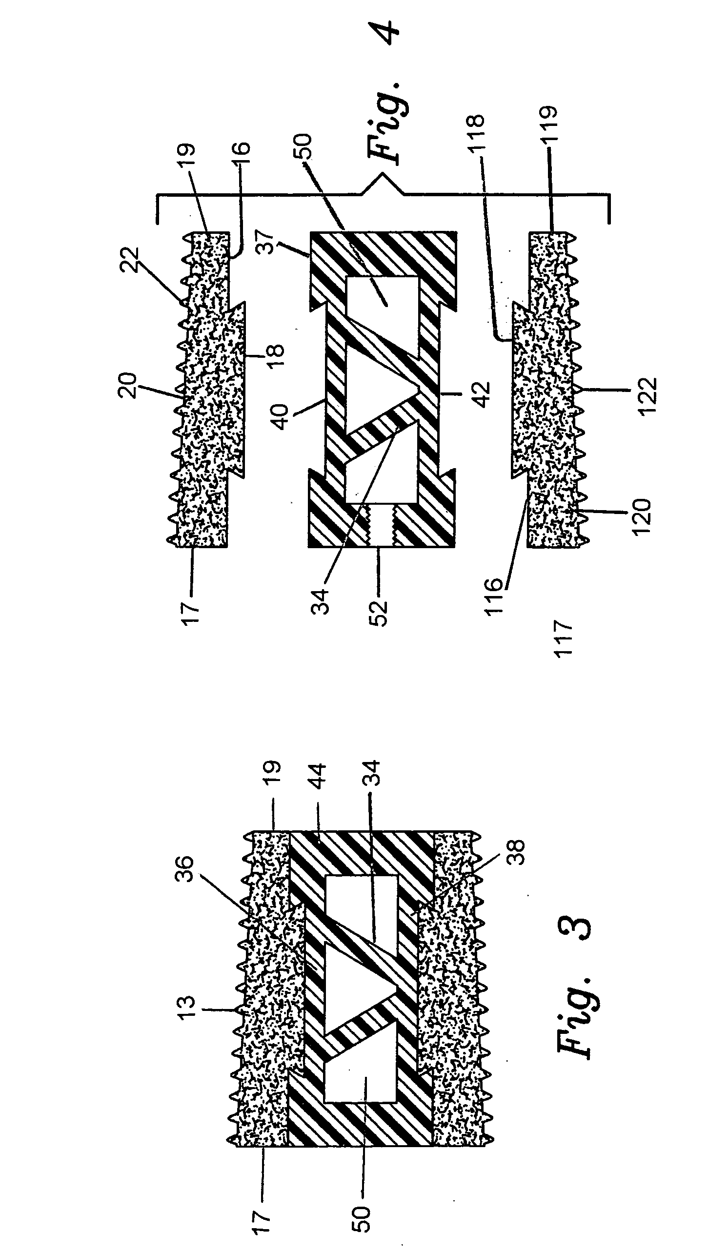
[0036]The preferred embodiment and best mode of the present invention is shown in FIGS. 1 through 4. The composite bone implant block 10 is shown in FIG. 1 in accordance with the present invention.

[0037]The composite cortical bone block body or intervertebral spacer 10 is preferably constructed with a first end cap member 12 constructed of cortical bone taken from donors cut into a ring shape. The cap member body 13 has an interior circular through going bore 14 formed or cut therein, and defines a flat planar bottom surface 16 which is provided with a dove tail shaped projection 18 which extends outward from the planar bottom surface 16. The cap body is tapered with the rear end 17 being of a greater height than the front end 19. The outer or top surface 20 which is tapered has a plurality of teeth 22 formed or cut into the exterior surface to provide a gripping surface on the adjacent vertebrae. The taper runs between 5° to 10° and the height of the upper cap member runs between 3...


PUM

PropertyMeasurementUnit
total load bearing forceaaaaaaaaaa
heightaaaaaaaaaa

Abstract

The invention is directed toward a sterile composite bone graft for use in implants comprising a central member constructed of biocompatible plastic with two end caps of cortical bone mated to opposite ends of the central member. The central member is cylindrically ring shaped with a plurality of ribs formed in the side wall of the cylinder.

Description

RELATED APPLICATION[0001]There are no related applications.STATEMENT REGARDING FEDERALLY SPONSORED RESEARCH OR DEVELOPMENT[0002]Not applicable.REFERENCE TO SEQUENCE LISTING, A TABLE OR A COMPUTER PROGRAM LISTING COMPACT DISC APPENDIX[0003]None.FIELD OF INVENTION[0004]The present invention is generally directed toward a surgical implant and more specifically is a shaped composite bone block implant having a synthetic central portion and allograft cortical end caps for the fusion of vertebral bones when the implant is introduced between adjacent vertebrae to be fused.BACKGROUND OF THE INVENTION[0005]The use of substitute bone tissue dates back around 1800. Since that time research efforts have been undertaken toward the use of materials which are close to bone in composition to facilitate integration of bone grafts. Developments have taken place in the use of grafts to use materials such as corals, hydroxyapatites, ceramics or synthetic materials such as biodegradable polymer material...

Claims


Application Information

Patent Timeline
Patent Type & Authority Applications(United States)
IPC IPC(8): A61F2/44
CPCA61F2/28A61F2/30734A61F2/4455A61F2/4465A61F2002/2817A61F2002/302A61F2310/00359A61F2002/30677A61F2002/30772A61F2002/4629A61F2220/0025A61F2230/0065A61F2310/00958A61F2002/30387
Inventor STEINER, ANTON J.THOMAS, GARYMCBRIDE, DENNIS
Owner MUSCULOSKELETAL TRANSPLANT FOUNDATIO
Why Eureka
Try Eureka