Space truss structure surface slab assembly

a technology of space trusses and surface slabs, which is applied in the direction of girders, instruments, vessel construction, etc., can solve the problems of low dynamic efficiency of processing plates in any type of materials, low productivity, and reduced thickness of hollow grid members, so as to achieve high strength, low cost, and economic production

Inactive Publication Date: 2008-07-03
SHOJI BUNICHI
View PDF17 Cites 16 Cited by
  • Summary
  • Abstract
  • Description
  • Claims
  • Application Information

AI Technical Summary

Benefits of technology

[0017]Thus, the present invention ensures economical production of a panel core material applicable to a large or massive structure obtained by volume production, and provides a truss structure surface slab assembly of high strength by reducing the pyramidal surface pitch. For example, it can be used to construct the hull partition and bulkhead of a ship, a floor, wall and roof body of a vehicle, and the floor, wall and roof of a building, without using a column or beam. It allows construction of a massive glass surface slab assembly, without using a metallic frame. The present invention provides these structures at extremely low costs.

Problems solved by technology

1) A processed plate in any type of material has a low dynamic efficiency for strength, and is characterized by a low productivity.
2) The surface slab thickness is increased if the hollow core material has a coarse grid pitch, and the thickness of the hollow grid member is decreased if the hollow core material has a fine grid pitch. Thus, the economic efficiency is very low for the required strength.
3) A urethane resin or honeycomb paper is used as the hollow material, but the scope of application is limited due to poor strength, and inflammability is a problem in the case of urethane.

Method used


Image

  • Space truss structure surface slab assembly
  • Space truss structure surface slab assembly
  • Space truss structure surface slab assembly

Examples


embodiment 1

[0047]A description of preferred embodiments will be provided with reference to the drawings:

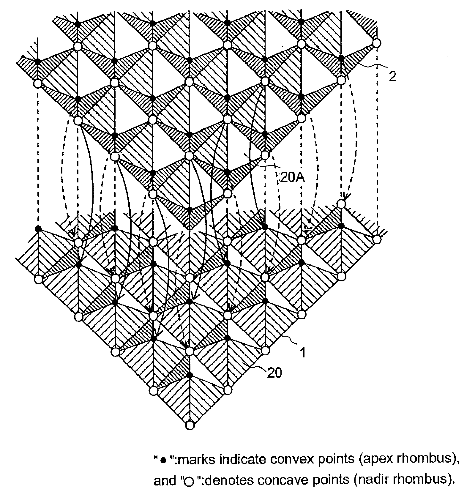
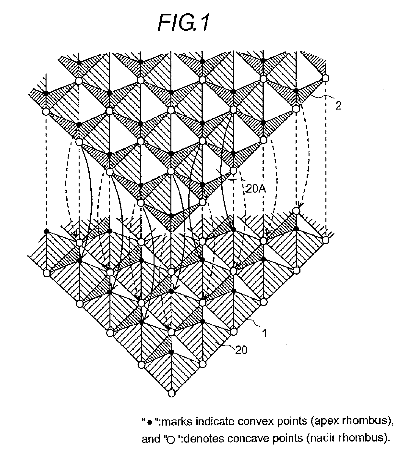
[0048]FIGS. 1 through 4 show a first embodiment of the present invention.

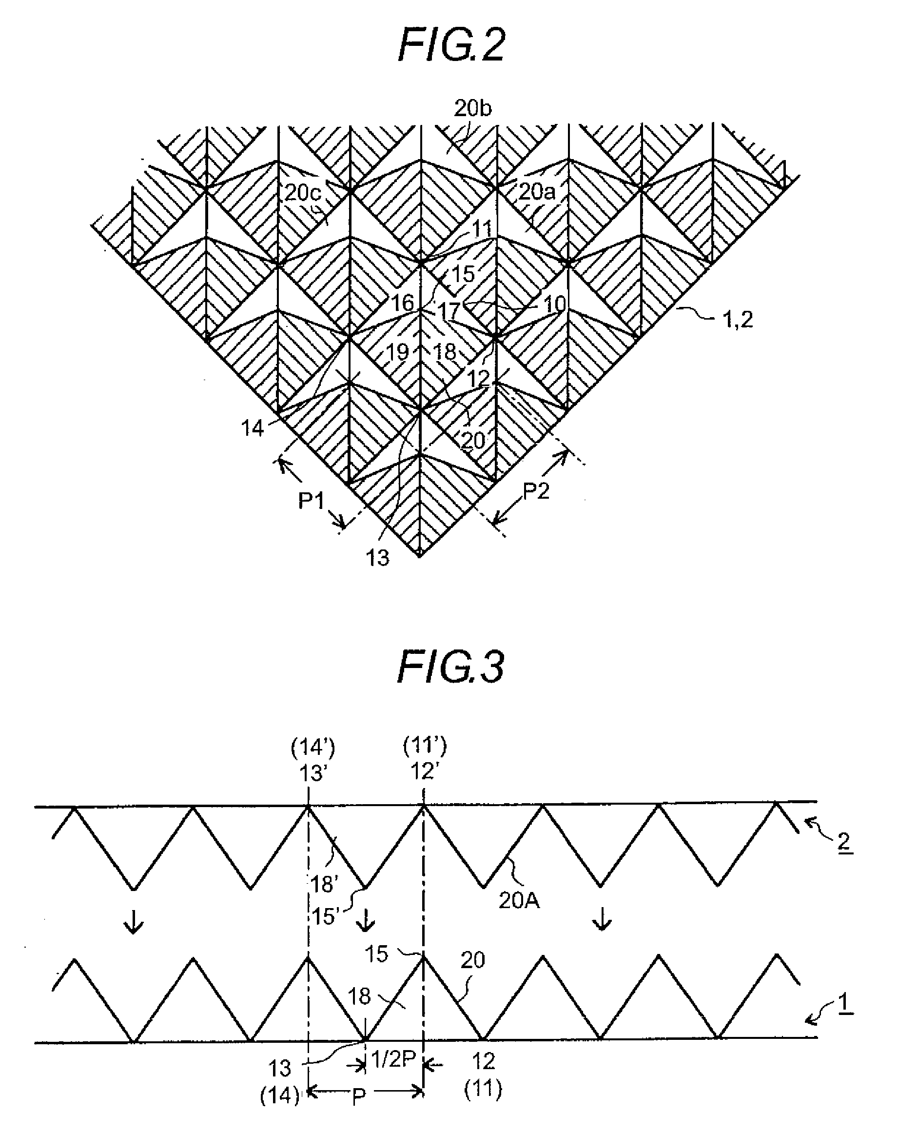
[0049]FIG. 1 shows how to configure a space truss structure surface slab assembly. FIG. 2 provides details of a partial view in FIG. 1. FIG. 3 shows a two-piece set of pyramidal surface slabs prior to assembling. FIG. 4 shows the assembly thereof as a first embodiment.

[0050]In FIG. 1, two pyramidal surfaces 1 and 2 are used to configure the space truss structure surface slab assembly.

[0051]Referring first to FIG. 2, the configuration of the pyramidal surface slabs 1 and 2 will be described. Pyramidal surface slabs 1 and 2 are fabricated from one of sheet material, for example, a metal sheet formed through injection processing by a stamping die. As will be described later, except for the metal sheet, a non-metallic material such as corrugated cardboard, lumber, plywood, plastics and glass can be used as a sheet material....

embodiment 2

[0065]FIGS. 7 through 9 show a second embodiment of the present invention. FIG. 7 shows the details of the pyramidal surface; while, FIGS. 8 and 9 show how to assemble a two-piece set of the pyramidal surface slabs used in the present embodiment.

[0066]To configure a space truss structure surface slab assembly, two pyramidal surface slabs 101 and 102 are used in a manner similar to that shown in FIG. 1. Referring to FIG. 7, the configuration of the pyramidal surface slabs 101 and 102 will be described. The pyramidal surface slabs 101 and 102 are produced from one plate-like material, for example, a metallic plate, by a molding operation using a stamping die.

[0067]As shown in FIG. 7, the pyramidal surface slabs 101 and 102 are delimited by plotting three nadir rhombuses 111, 112 and 113. An apex rhombus 115 is delimited above the center point of a triangle 110, and each of the nadir rhombuses 111, 112 and 113 and the apex rhombus 115 are plotted to form a group of pyramidal surfaces p...

embodiment 3

[0077]FIG. 10 shows an example of a third embodiment in which a pyramidal surface slab containing a hexagonal pyramidal surface is employed. FIGS. 10 through 13 show the details of the third embodiment. FIG. 10 shows how to configure a space truss structure surface slab assembly, and FIG. 11 shows details thereof in a partial view of FIG. 10. FIG. 12 and FIG. 13 show how to assemble a two-piece set of pyramidal surface slabs used in the present embodiment.

[0078]In FIG. 10, two sets of pyramidal surface slabs 1 and 2 are used to configure a space truss structure surface slab assembly.

[0079]Referring to FIG. 11, the configuration of the pyramidal surface slabs 1 and 2 will be described. The pyramidal surface slabs 1 and 2 are produced from one plate-formed material—for example, sheet metal—by a molding operation using a stamping die. As shown in FIG. 11, an apex rhombus 47 is delimited over the center point of a hexagon 40 that is delimited by plotting six nadir rhombuses 41, 42, 43, ...


PUM

PropertyMeasurementUnit
thicknessaaaaaaaaaa
heightaaaaaaaaaa
diameteraaaaaaaaaa

Abstract

An apex rhombus is delimited over the center point of a square, which is delimited by plotting four nadir rhombuses on the same plane, and each of the nadir rhombuses and the apex rhombus are jointed to form a group of pyramidal surfaces equipped with four planar slopes having substantially the same height in a pyramidal form. Two pyramidal surface slabs are assembled, each composed of pyramidal surfaces around one pyramidal surface, each sharing one nadir rhombus, adjacent each other, and arranged in a grid pattern at an equal pitch in plural directions. The pyramidal surfaces arranged in a grid pattern are each displaced by one-half pitch in a specific direction, such that the apex rhombus of one of the pyramidal surface comes in contact with the nadir rhombus of the other pyramidal surface, whereby the two pyramidal surfaces are placed one on the other.

Description

CROSS-REFERENCE TO RELATED APPLICATION[0001]This application is a divisional application of U.S. application Ser. No. 11 / 066,301, filed Feb. 28, 2005, the contents of which are incorporated herein by reference.FIELD OF THE INVENTION[0002]The present invention relates to a space truss structure surface slab assembly.BACKGROUND OF THE INVENTION[0003]The Japanese Application Patent Laid-open Publication No. 10-181593 discloses the structure of a rolling stock car body. This structure is made of a plurality of aluminum alloy hollow extruded members having a closed cross section, and it comprises an outer plate, an inner plate, and a partition for holding these plates at a predetermined spaced interval and jointing them to form a triangle.[0004]The Japanese Application Patent Laid-open Publications No. 3340533 describes a truss panel type core material, wherein sheet materials consisting of a wooden single plate or plywood sheet are combined to form a truss, as seen when its cross sectio...

Claims


Application Information

Patent Timeline
Patent Type & Authority Applications(United States)
IPC IPC(8): E04C3/02E04B1/18E04B5/18E04B1/32B32B3/28B62D33/04B63B3/48B63B3/56B64C1/00E04B1/19E04B5/02E04B5/10E04C2/32F16S3/04G02B5/124
CPCB62D33/046E04B1/19E04B5/04E04B2001/199E04B2001/1984E04B2001/1987E04B2001/1981
Inventor SHOJI, BUNICHI
Owner SHOJI BUNICHI
Why Eureka
Try Eureka