Easy cut suspension grid

a technology of suspension grid and grid elements, which is applied in the direction of girders, joists, trusses, etc., can solve the problems of no practical or cost-effective way to prefabricate an installation or even a part of an installation, no convenient workbench or like table to support the grid elements, and no installation work can be done on the actual floor surface or by an installer standing directly on the floor. , to achieve the effect of reducing labor intensity, reducing

Inactive Publication Date: 2008-07-03
USG INTERIORS INC
View PDF25 Cites 4 Cited by
  • Summary
  • Abstract
  • Description
  • Claims
  • Application Information

AI Technical Summary

Benefits of technology

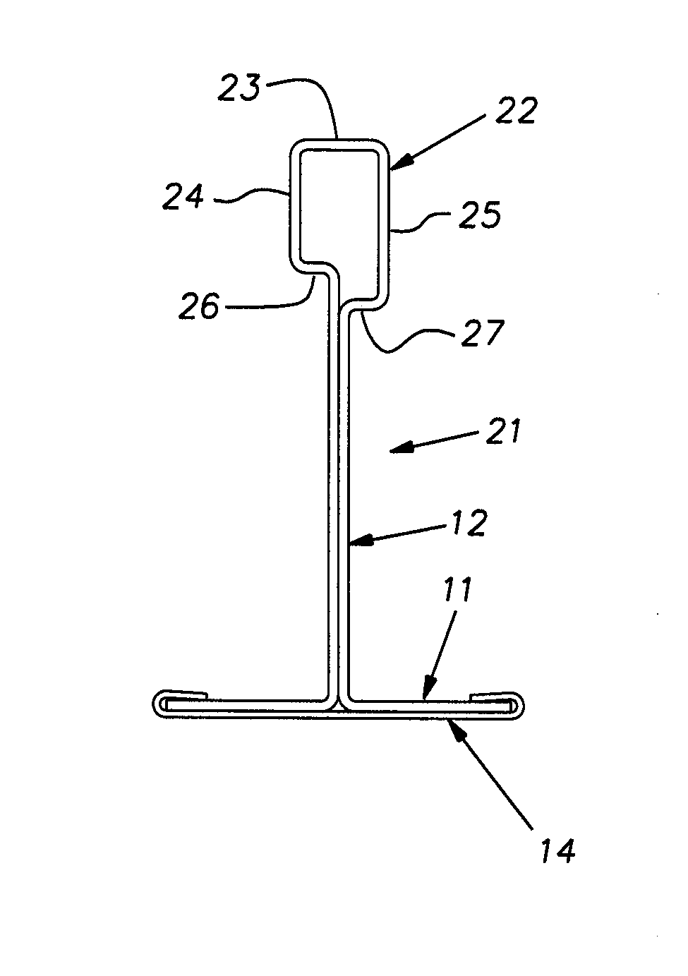
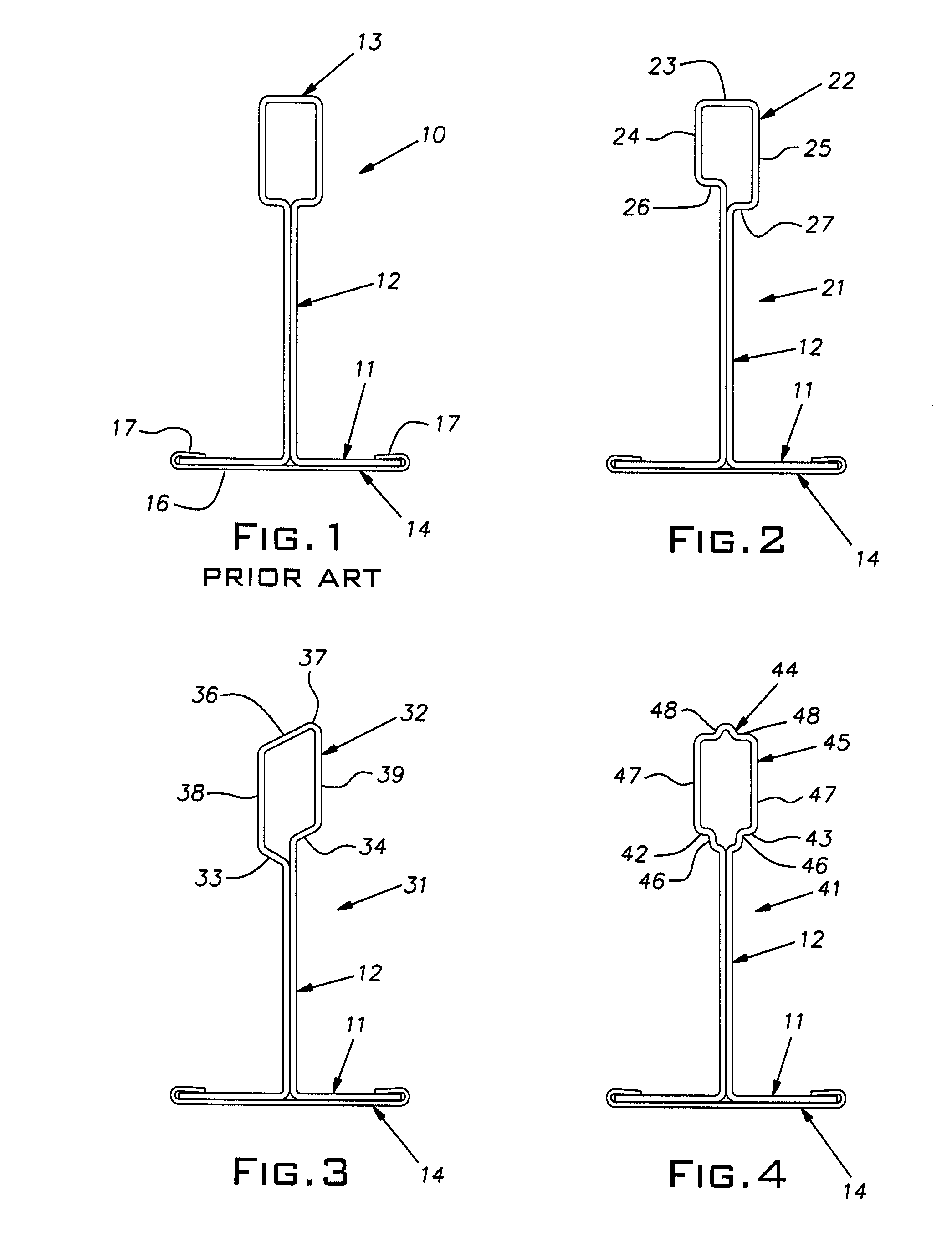
[0003]The invention provides a grid tee that can be manually cut with reduced effort and thereby makes its installation easier, resulting in the technician or installer experiencing less fatigue and, potentially, greater productivity.
[0004]More specifically, the invention brings the insight that a major source of resistance of a grid tee to being cut is the compressive strength of the typical hollow reinforcing bulb formed at the upper part of the tee. With still greater insight, the invention recognizes that the gripping force required of a technician using the usual pair of snips is related to the compression strength of the bulb structure, as distinguished from the compressive strength of the bulb material per se, at the point furthest from the pin joint of the pair of pivoted blades in the snips. The base area of the bulb is the part of the tee encountered by the blades that is furthest from the pivot pin of the hand snips when the initial effort is made to cut the top of the tee. This area, therefore, has a relatively large lever arm of resistance measured from the pivot point of the snips and thus can create a high resistance to the closing snip's blades and prevent the metal stock of the tee to be sheared easily.
[0005]The invention reduces the problem of high forces that are otherwise ordinarily necessary to manually cut a tee. This is accomplished according to the invention by incorporating certain structure / geometry in the base of the bulb, the location of the tee structure that is the greatest distance from the pivot pin of the snips when the bulb is being cut. These structures are used to more readily initiate buckling or crushing of the bulb base area when it is subjected to the lateral compressive forces being applied by the snip blades. Once the bulb has been crushed and flattened by the blades, the blades can shear the bulb stock more readily, especially if the snips are urged forwardly into the actual cutting zone, thereby keeping the leverage of the handles high.

Problems solved by technology

Ceiling grid is erected on site, there ordinarily being no practical or cost-effective way to prefabricate an installation or even a part of an installation.
Moreover, it is obvious that the installation work cannot be done on the actual floor surface or by an installer standing directly on the floor.
In this situation, there is typically no convenient workbench or like table to support the grid elements while length measurements are being made and transferred to a grid tee and while a grid tee is actually being cut to the proper length.
Repetitive manual cutting of tees in the customary manner can lead to fatigue in the installer's hand and a consequent loss of productivity.

Method used


Image

  • Easy cut suspension grid
  • Easy cut suspension grid

Examples


Embodiment Construction

[0010]FIG. 1 illustrates a traditional prior art grid tee or runner 10 in profile or cross-section. This prior art style grid tee 10 and the grid tees described hereinbelow incorporating the present invention are elongated shafts assembled into a rectangular gridwork typically suspended from overhead or superstructure and on which tiles are mounted to construct a suspended ceiling. The gridwork, typically, comprises main tees and intersecting cross tees; grid modules are typically 2 foot by 2 foot or 2 foot by 4 foot or metric equivalent. The main tees are provided with regularly spaced slots in their mid-section or web that accept connectors provided on the ends of cross tees as is customary in the industry. Main tees are connected end-to-end with suitable end connectors, known in the art, to span the ceiling area. The main and cross tees can have the same cross section or profile or the cross tees can have a lighter duty section such as having a reduced height.

[0011]The grid tee 1...


PUM


Abstract

A grid runner for a suspended ceiling having a lower flange extending generally horizontally, a web extending upwardly from the flange, and walls forming a hollow reinforcing bulb at the upper end of the web, the web lying generally in an imaginary vertical plane, a portion of the walls forming the bulb being disposed on and laterally spaced from the imaginary vertical plane, a wall area of the bulb on an upper side of the bulb bridging the space between the bulb walls on opposite sides of the imaginary plane, the bulb having lower wall portions forming its base and configured such that the bulb will readily collapse at the base when a lateral shear force is applied to the bulb walls by a hand-operated snips whereby the force to manually field cut the tee is reduced.

Description

BACKGROUND OF THE INVENTION[0001]The invention pertains to suspended ceiling grid and, in particular, to a grid runner construction that eases the task of its installation.PRIOR ART[0002]Suspended ceiling grid typically is in the form of metal runners having an inverted tee cross-section. Ceiling grid is erected on site, there ordinarily being no practical or cost-effective way to prefabricate an installation or even a part of an installation. Moreover, it is obvious that the installation work cannot be done on the actual floor surface or by an installer standing directly on the floor. Rather, a technician or installer works off a rolling scaffold or other elevating appliance. In this situation, there is typically no convenient workbench or like table to support the grid elements while length measurements are being made and transferred to a grid tee and while a grid tee is actually being cut to the proper length. It is axiomatic that time is money and the quicker and easier a piece ...

Claims


Application Information

Patent Timeline
Patent Type & Authority Applications(United States)
IPC IPC(8): E04C3/04E04B9/00
CPCE04B9/068E04C3/07E04C2003/0452E04C2003/043E04C2003/0421
Inventor WENDT, ALAN C.
Owner USG INTERIORS INC
Why Eureka
Try Eureka