Apparatus, system, and method for exhaust aftertreatment efficiency enhancement

a technology of exhaust aftertreatment and efficiency enhancement, which is applied in the direction of machines/engines, process and machine control, instruments, etc., can solve the problems of inability to reconfigure in real time, excessive use of scr reagents (usually urea or ammonia), and over-designed systems that operate at low efficiency in many operating conditions for many applications. , to achieve the effect of enhancing the efficiency of an aftertreatment system

Active Publication Date: 2008-07-03
CUMMINS FILTRATION IP INC
View PDF8 Cites 35 Cited by
  • Summary
  • Abstract
  • Description
  • Claims
  • Application Information

AI Technical Summary

Benefits of technology

[0010]The present invention has been developed in response to the present state of the art, and in particular, in response to the problems and needs in the art that have not yet been fully solved by currently available particulate filter

Problems solved by technology

These devices typically have the property that they cannot be reconfigured in real time, and therefore must be designed such that the engine system can meet emissions regulations at all operating points.
While this method makes an emissions compliant engine, it produces an over-designed system that operates at a low efficiency in many operating conditions for many applications.
The result of this is that at many operating conditions, the DOC converts too much NO to NO2, resulting in excessive use of the SCR reagent (usually urea or ammonia) as the SCR system operates at non-optimal

Method used


Image

  • Apparatus, system, and method for exhaust aftertreatment efficiency enhancement
  • Apparatus, system, and method for exhaust aftertreatment efficiency enhancement
  • Apparatus, system, and method for exhaust aftertreatment efficiency enhancement

Examples


Embodiment Construction

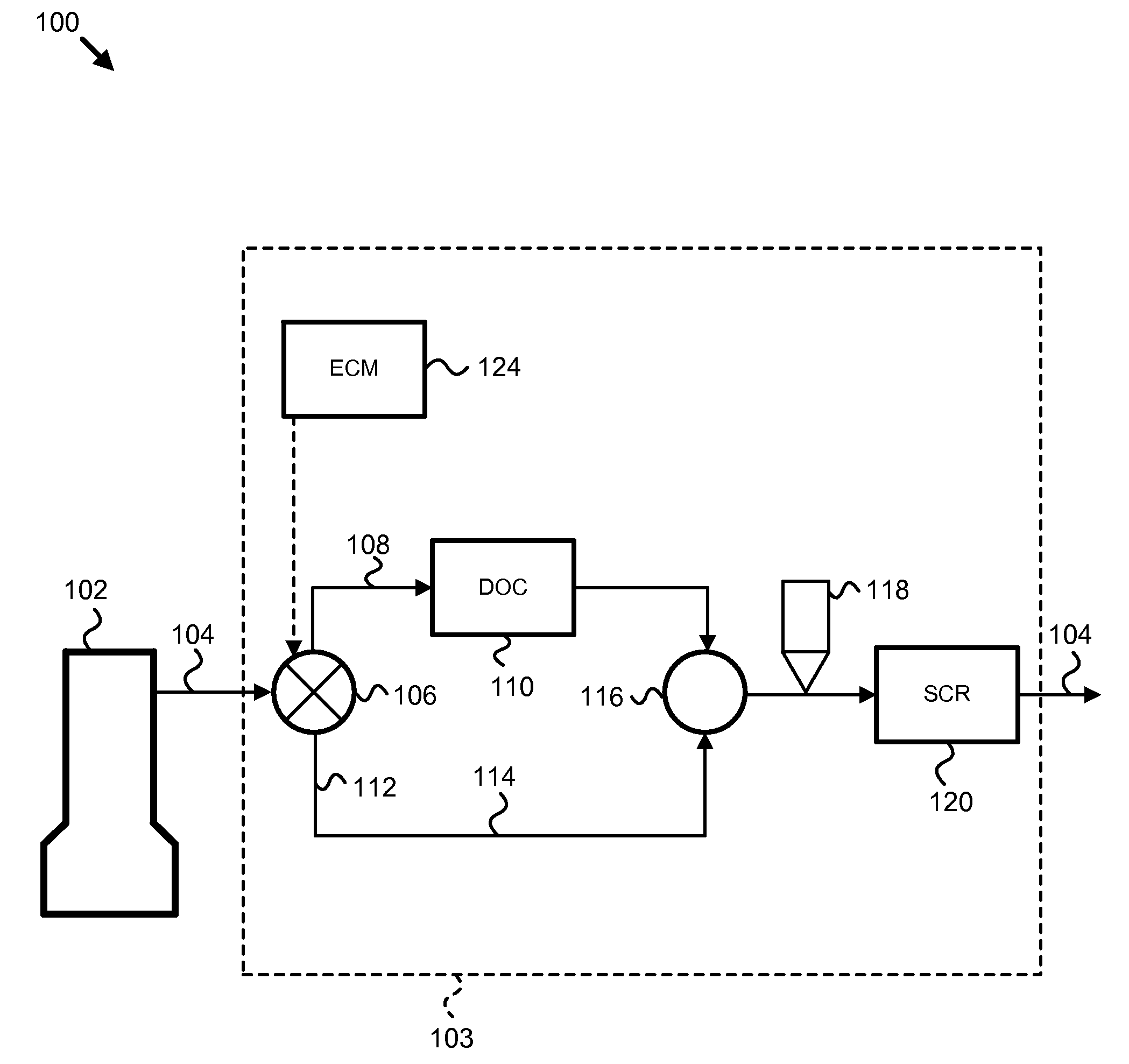
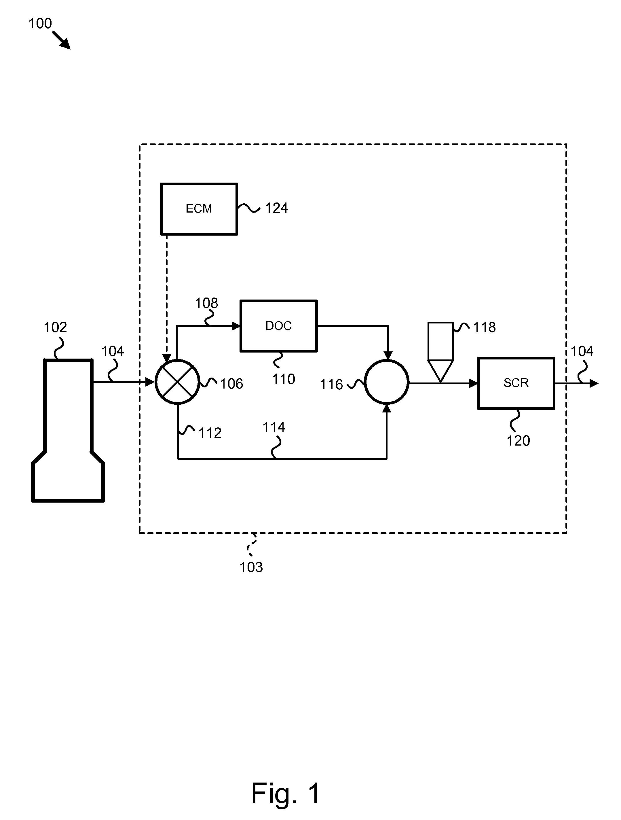
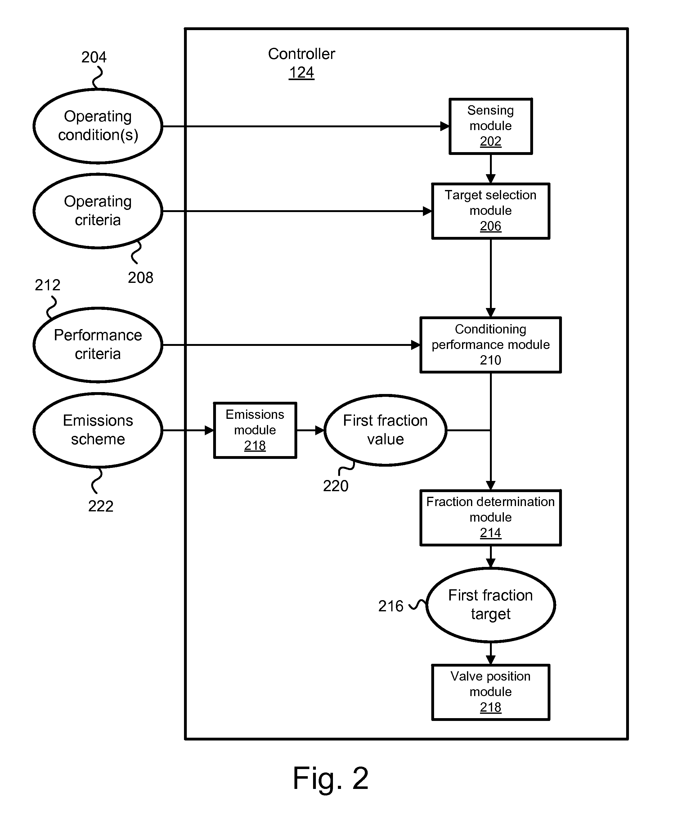
[0043]It will be readily understood that the components of the present invention, as generally described and illustrated in the figures herein, may be arranged and designed in a wide variety of different configurations. Thus, the following more detailed description of the embodiments of the apparatus, system, and method of the present invention, as presented in FIGS. 1 through 17, is not intended to limit the scope of the invention, as claimed, but is merely representative of selected embodiments of the invention.

[0044]Reference throughout this specification to “one embodiment” or “an embodiment” means that a particular feature, structure, or characteristic described in connection with the embodiment is included in at least one embodiment of the present invention. Thus, appearances of the phrases “in one embodiment” or “in an embodiment” in various places throughout this specification are not necessarily all referring to the same embodiment.

[0045]Furthermore, the described features,...


PUM


Abstract

An apparatus, system, and method are disclosed for enhancing the efficiency of an exhaust aftertreatment application. The method may include determining the current operating conditions of the application, the optimal operating conditions of a target component, and the performance criteria of a conditioning component relative to the optimal operating conditions. The method may include determining an optimal fraction of an exhaust flow to pass through the conditioning component to achieve the optimal operating conditions of the target component. The method may further include manipulating a bypass valve position based on the optimal fraction of exhaust flow to pass through the conditioning component. The target component may be a selective catalyst reduction (SCR) component that operates optimally at a designed NO2/NOx mole ratio. The conditioning component may be a diesel oxidation catalyst (DOC) that affects the NO2/NOx mole ratio. A method is thereby provided to operate an exhaust aftertreatment application more efficiently relative to an application without the invention.

Description

BACKGROUND OF THE INVENTION[0001]1. Field of the Invention[0002]This invention relates to the efficient operation of engine aftertreatment systems, and more particularly relates to aftertreatment systems comprising a diesel particulate filter or a selective catalytic reduction system.[0003]2. Description of the Related Art[0004]Diesel emissions regulations are driving many modern diesel engine systems to utilize aftertreatment devices to clean up exhaust emissions downstream of the engine. These devices typically have the property that they cannot be reconfigured in real time, and therefore must be designed such that the engine system can meet emissions regulations at all operating points. In practical terms, this typically means that the aftertreatment devices are configured to treat the full engine exhaust at rated operation, or maximum load on the engine system.[0005]While this method makes an emissions compliant engine, it produces an over-designed system that operates at a low ...

Claims


Application Information

Patent Timeline
IPC IPC(8): F01N3/20F01N3/021F01N3/035
CPCF01N3/035F01N3/106F01N3/2053F01N3/2066F01N13/009F01N2410/00F01N2610/02Y02T10/24F01N3/208Y02T10/12
Inventor SALEMME, GARYMOHAMMED, HASAN
Owner CUMMINS FILTRATION IP INC
Why Eureka
Try Eureka