
Method for transporting bent, irregularly shaped pieces of scrap sheet metal

a technology of scrap sheet metal and scrap metal, which is applied in the direction of press, process efficiency improvement, manufacturing tools, etc., can solve the problems of insufficient force to withstand secondary impact or force, and achieve the effect of reducing the volume of space occupied, reducing the cost of transportation, and simplifying processing

Inactive Publication Date: 2008-07-03
SOAVE ENTERPRISES
View PDF4 Cites 12 Cited by
  • Summary
  • Abstract
  • Description
  • Claims
  • Application Information

AI Technical Summary

Benefits of technology

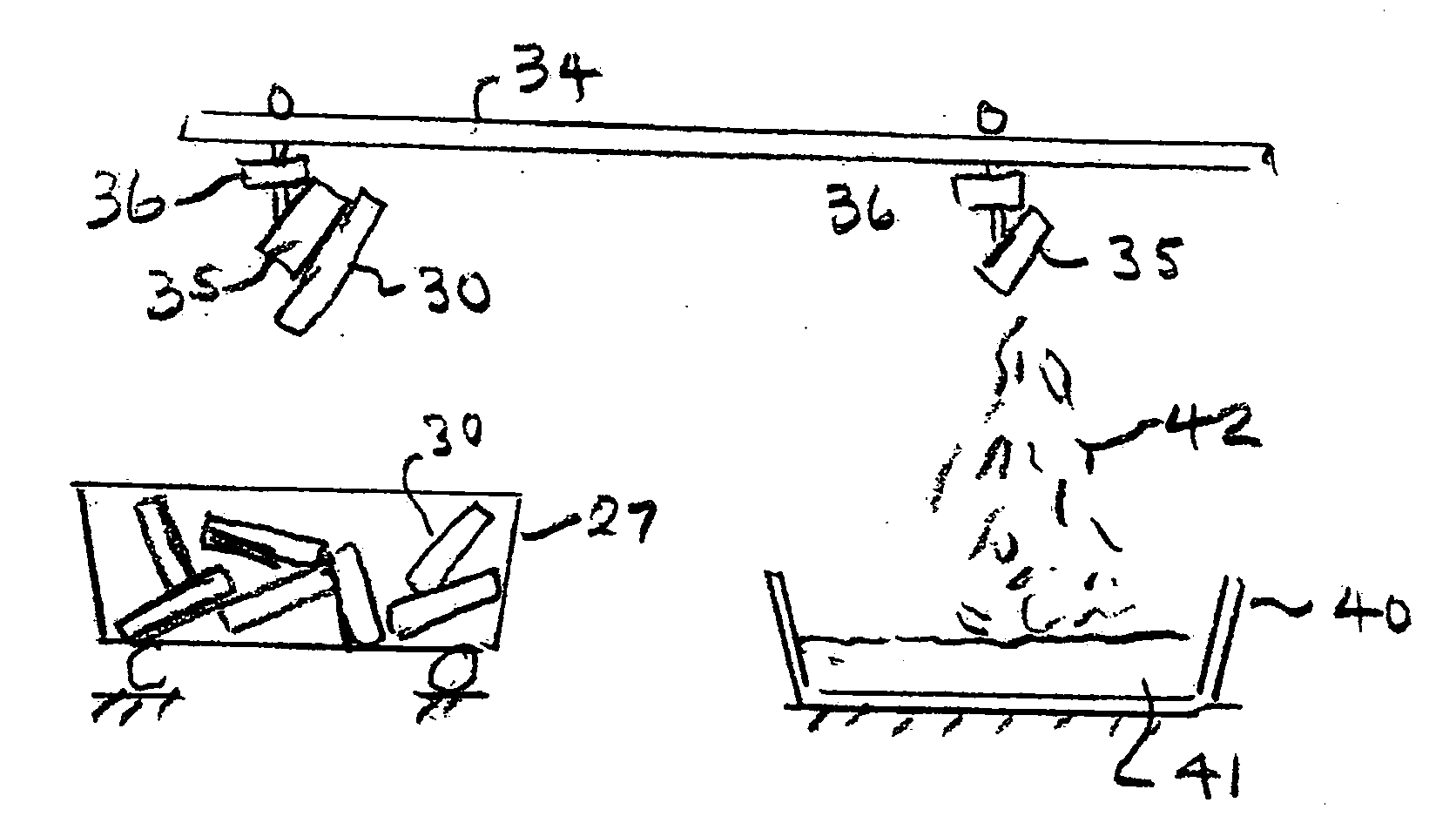
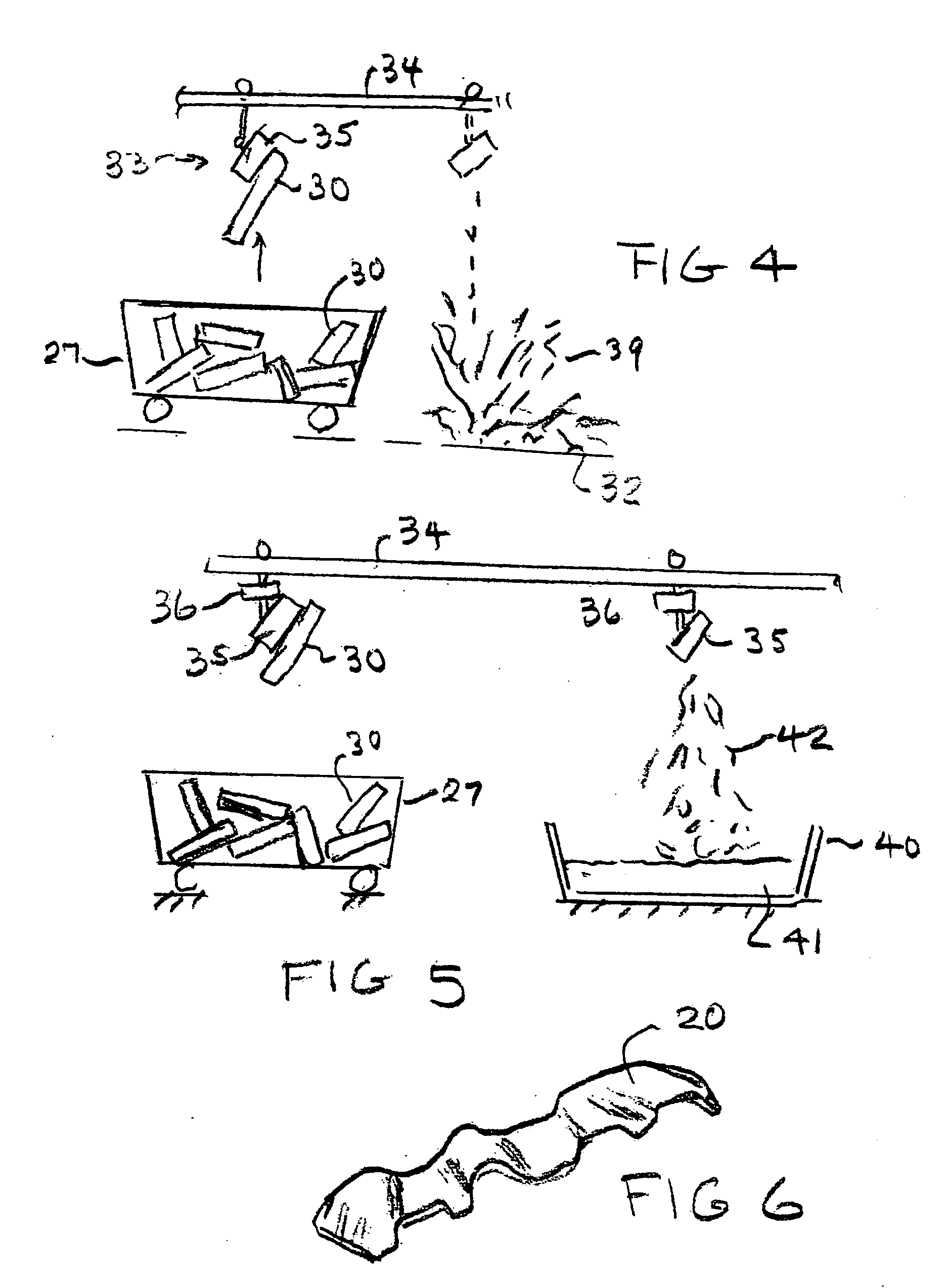
[0010]The method herein contemplates transporting large quantities of irregularly shaped, bent or sized thin, scrap, sheet metal pieces that are generated in various conventional, industrial manufacturing processes. The method involves forming a batch of loose pieces and flattening and compacting the pieces together into relatively thin wafers by a force that is sufficient to bind adjacent pieces together temporarily. The force is insufficient to withstand a secondary impact or force that is later applied to the assembled wafer, after the wafer is transported. Thus, wafers, one by one, may be formed and then transported from the site where the scrap is generated to a remote site where the metal is to be processed for recycling. At that site, the wafers are disassembled by applying the secondary force to each wafer. The secondary force may be applied to dropping the wafers from a predetermined height upon a firm support, such as the ground, so that the constituent pieces of the wafer separate for melting purposes. Thus, the benefits of reducing the volume of space occupied by the scrap metal pieces for transportation purposes and the benefits of melting separate pieces are both provided. Consequently, the expenses, time, and equipment needed for transporting large volumes of scrap material and for recycling the scrap material are reduced and the processing is simplified.
[0011]A significant object of the present invention is to enable the efficient removal of large quantities of bulky scrap sheet metal pieces from a factory which processes sheet metal into various industrial products and to provide a relatively inexpensive system for transporting the scrap sheet metal pieces to a remote site where the scrap pieces may be recycled by melting the material.
[0012]Another object of this invention is to utilize compacting equipment to provide a force to produce relatively thin, temporary, compacted wafers formed of a batch of bent and irregularly shaped and sized pieces of scrap sheet metal, for transporting the wafers in suitable containers or vehicles to a remote site where the wafers may be easily disassembled by applying a secondary force to each of waver, such as by lifting it above a ground surface and gravity dropping it or by otherwise impacting the wafer. Vibration force may also be applied to the wafers to assist in separating the pieces.
[0013]Still another object of this present invention is to provide a method for substantially reducing the volume of space needed for transporting large numbers of irregularly shaped, sized and bent pieces of scrap sheet metal, for reducing the amount of transportation equipment needed for moving the scrap to a remote site for recycling the metal, while still providing the pieces in their separate condition for melting the metal.
[0014]A further object of this invention is to increase the value of large quantities of scrap sheet metal pieces by providing a method for economically delivering individual pieces to metal recycling melt furnaces while economically transporting the pieces from the site at which they were generated to the recycling site.

Problems solved by technology

The force is insufficient to withstand a secondary impact or force that is later applied to the assembled wafer, after the wafer is transported.

Method used


Image

  • Method for transporting bent, irregularly shaped pieces of scrap sheet metal
  • Method for transporting bent, irregularly shaped pieces of scrap sheet metal
  • Method for transporting bent, irregularly shaped pieces of scrap sheet metal

Examples


Embodiment Construction

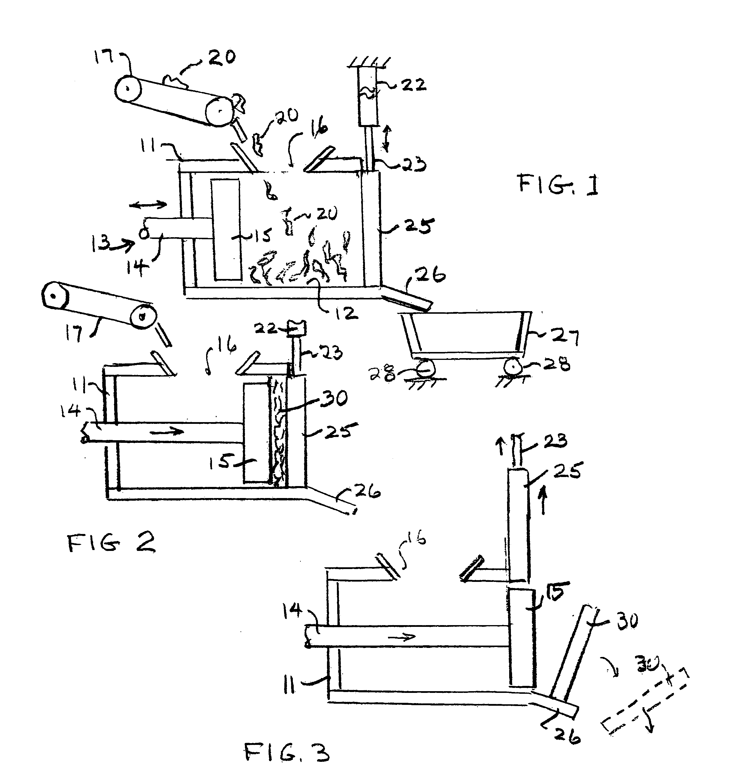
[0023]The attached drawings schematically illustrate a compacter 10 which comprises a housing 11 within which a compression chamber 12 is provided. A reciprocating ram 13, preferably powered by a suitable hydraulic system, not shown, includes a drive shaft 14 upon which a ram pressure head 15 is mounted. The ram reciprocates within the housing and through the compression chamber as will be described below.

[0024]The housing has an entrance hopper 16 located beneath the exit portion of a feed conveyor 17. The conveyor 17 may consist of a number of conveyors, arranged end to end, which carry scrap metal pieces from within a factory building containing manufacturing equipment, such as stamping presses, punch presses, shears, etc. which, in one way or another, operates upon sheet material and in so doing produces scrap in the form of trimmings, punched out portions, etc. Pieces of scrap designated by the numeral 20 (see FIG. 6), resulting from the industrial process within the factory, a...


PUM

PropertyMeasurementUnit
widthaaaaaaaaaa
heightaaaaaaaaaa
pressureaaaaaaaaaa

Abstract

A method for transporting large quantities of convoluted, multiply bent, irregularly shaped, pieces of scrap metal from the location where they are produced to a remote location where the metal may be recycled, comprises flattening and temporarily binding together a batch of such pieces into an assembled wafer. The binding is produced by applying a compressive force of sufficient intensity to temporarily interconnect the pieces together but of insufficient intensity to interconnect the piece tightly enough to resist disassembly of the wafer upon impacting the assembled wafer. After the formation of a wafer comprising the interconnected numerous pieces, the wafer is transported to a remote site for recycling the metal. At such remote site, the wafer is disassembled into its constituent pieces by applying an impact to the wafer of sufficient intensity to cause the disengagement of the pieces for disassembling the wafer. The impact may be applied by dropping the wafers from a predetermined height above a ground surface for gravity falling and striking against the surface. The force of the impact may be assisted by vibrating the wafer when it is raised above the surface.

Description

BACKGROUND OF THE INVENTION[0001]This invention relates to a method for transporting large quantities of bent, irregularly shaped, pieces of scrap sheet metal from a site where the scrap is generated in a manufacturing process to a remote site where the pieces may be processed for recycling the metal.[0002]Industrial processes which utilize sheet metal to form useful parts by stamping or punching or drawing sheet metal generate large quantities of scrap metal pieces. These scrap pieces, which may constitute trimmings or other unused portions of initially flat sheet, are typically bent or convoluted and irregular in shape or size. It is common to collect and transport such loose, scrap metal pieces, for transporting them to a site where the metal pieces may be recycled, such as by melting them in a conventional electrical melt furnace.[0003]Transporting loose, multiply bent or convoluted pieces is a problem because each piece occupies a considerable volume of space. Therefore, the am...

Claims


Application Information

Patent Timeline
Patent Type & Authority Applications(United States)
IPC IPC(8): B30B5/00
CPCB30B9/3096B30B9/327C22B7/005C22B1/248B30B9/328Y02P10/20
Inventor HERING, ALFRED GEORGE
Owner SOAVE ENTERPRISES
Learn More