Method and apparatus for destroying or incapacitating improvised explosives, mines and other systems containing electronics or explosives

a technology of improvised explosive devices and methods, which is applied in the field of explosive deterrence, can solve the problems of detonating the target ied or mine, destroying or disabling the operation of these electronic circuits, and rapid temperature increas

Inactive Publication Date: 2008-07-03
VOSS SCI
View PDF24 Cites 35 Cited by
  • Summary
  • Abstract
  • Description
  • Claims
  • Application Information

AI Technical Summary

Benefits of technology

[0022]A primary advantage of the present invention is that it can be used with a broad range of IEDs or land mines.
[0023]Another advantage of the present invention is that it can be used to disable or destroy electronic or electrical systems in general, including those not associated with IEDs or land mines.
[0024]Other objects, advantages and novel features, and further scope of applicability of the present invention will be set forth in part in the detailed description to follow, taken in conjunction with the accompanying drawings, and in part will become apparent to those skilled in the art upon examination of the following, or may be learned by practice of the invention. The objects and advantages of the invention may be realized and attained by means of the instrumentalities and combinations particularly pointed out in the appended claims.

Problems solved by technology

For example, due to sufficient ohmic losses in the volume containing the IED or mine, or adequate ohmic losses in electrical wires internal to the IED or mine, a rapid temperature increase will occur and detonate the target IED or mine.
In addition, the high-voltage dispersed around the target and high currents flowing through the target volume will directly couple to the electronic circuits of a mine or IED and destroy or disable the operation of these electronic circuits that are required for IED and mine operation.
Further, the high voltage dispersed around the target and high currents flowing through the target will disrupt electronic systems associated with the IED or land mine such that energy stored in the circuits or batteries within the IED or land mine are discharged into explosive elements, such as detonators, or into the IED's or land mine's explosive material.
This energy can lead to the detonation of the IED or mine.
None of the prior art has disclosed a method and apparatus utilizing direct injected electrical energy into the earth to destroy or disable IEDs or land mines.

Method used


Image

  • Method and apparatus for destroying or incapacitating improvised explosives, mines and other systems containing electronics or explosives
  • Method and apparatus for destroying or incapacitating improvised explosives, mines and other systems containing electronics or explosives
  • Method and apparatus for destroying or incapacitating improvised explosives, mines and other systems containing electronics or explosives

Examples


Embodiment Construction

Best Modes for Carrying Out the Invention

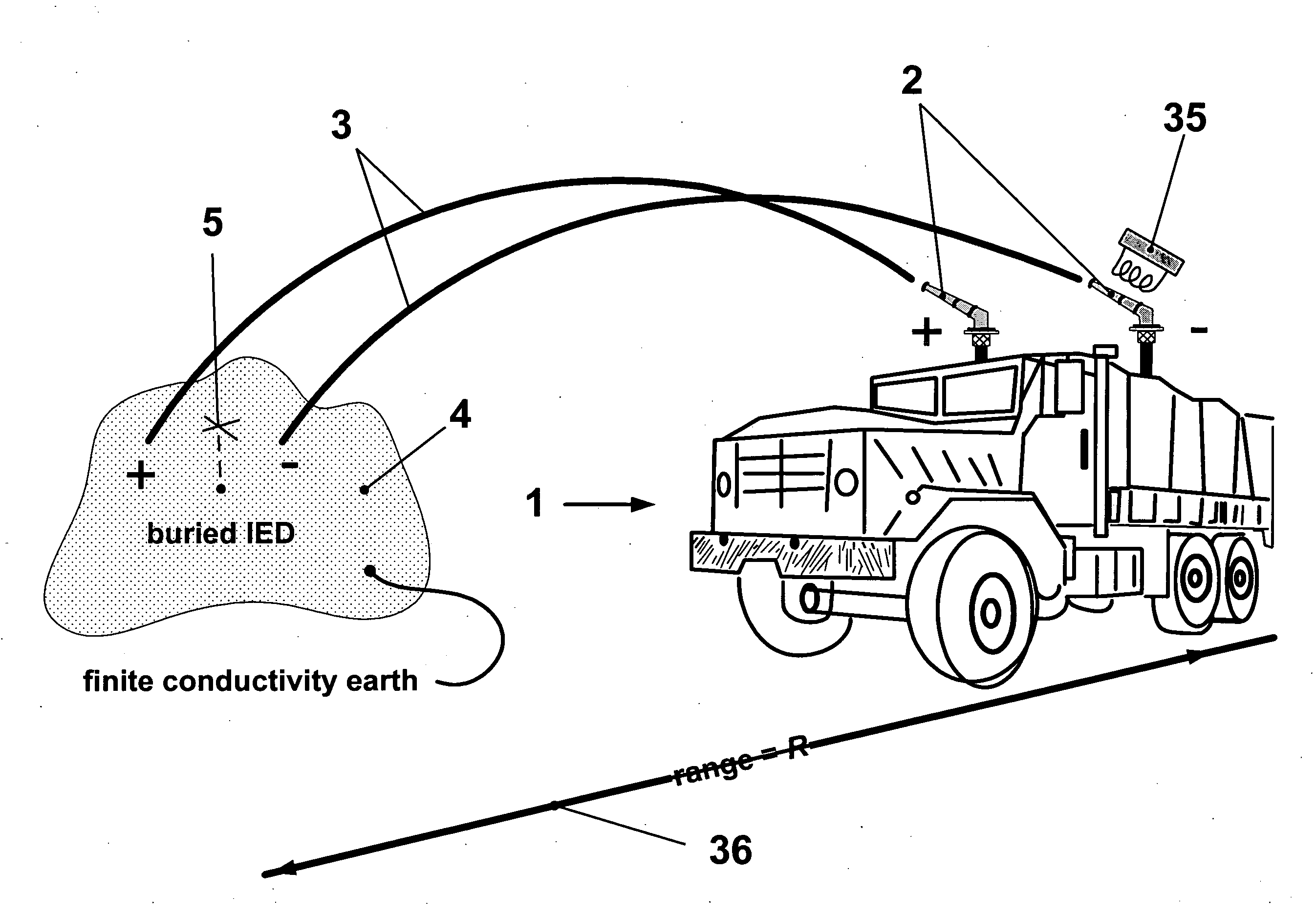
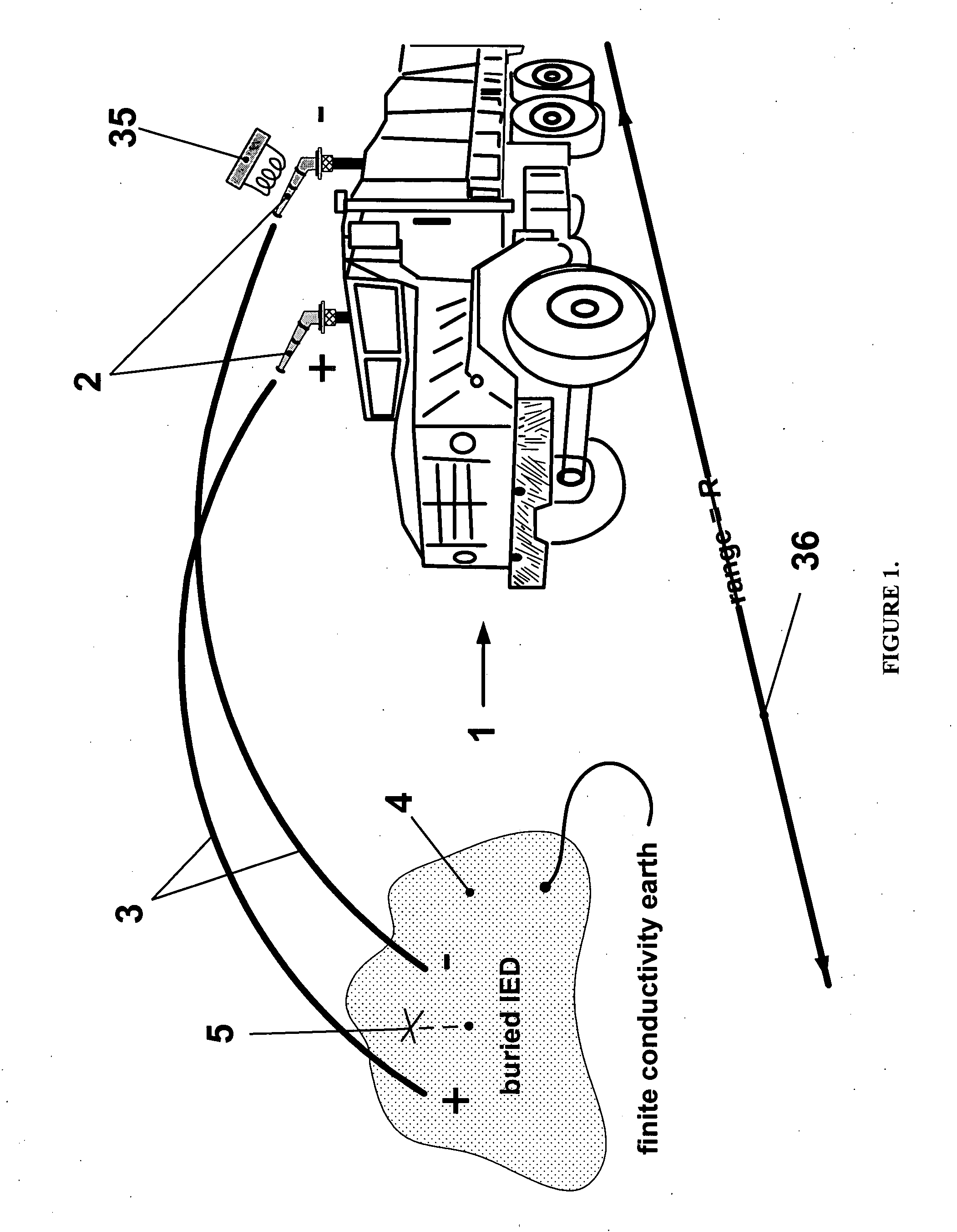
[0034]FIG. 1 shows a carrier machine 1, whose purpose is to support and transport all sub-systems required by the Electric Cannon for operation. In this case carrier machine 1 is a platform, or vehicle, which carries electrical prime power (not shown), a high voltage generator (not shown), a high voltage switch (not shown) a water reservoir (not shown), command and control sub-system (not shown) and a water projection system 2. Also indicated in the illustration of FIG. 1, is a target area 4 that is down range of the Electric Cannon. Target area 4 is shown to contain a buried IED or mine 5. Also indicated in FIG. 1 is how transmission line 3 (in this case a parallel, two wire transmission line constituted of a conductive liquid solution) lands astride target area 4. Carrier machine 1 is also intended to house and protect one or more human operators. FIG. 1 also shows two water launching apparatuses such as electric cannons 2 whose purpose and...


PUM


Abstract

A technique and apparatus for generating high voltage (100s-1000s kV) and supplying high current (fractional to many tens of kilo-amperes), projecting a parallel, two wire electrical transmission line over a large distance (10s-100s m), or a single conductor in which the return path is the earth, which is capable of sustaining high voltages and conducting high currents, and landing the terminating terminals of the transmission line across a pre-defined target zone resulting in a low impedance closure of the electrical circuit causing high electrical current to flow. The applications for the present invention, which falls into a class of directed energy and/or non-lethal device, include: suppression of Improvised Explosive Devices (IED) and landmines; halting motorized platforms, including two and four wheeled motor vehicles and boats; damage and destruction of electronic systems; and destruction or incapacitation of electronic systems at substantial distances from a high voltage device.

Description

CROSS-REFERENCE TO RELATED APPLICATIONS[0001]This application is based on U.S. Provisional Application Ser. No. 60 / 817,044, entitled “Electric Water Cannon,” filed on Jun. 28, 2006, the teachings of which are incorporated herein by reference.BACKGROUND OF THE INVENTION[0002]1. Field of the Invention (Technical Field)[0003]The present invention relates to explosive deterrence and more particularly to an apparatus and method to destroy or incapacitate the operation of improvised explosive devices (IEDs), mines or electronic systems that lie on or below the surface of the earth, or in structures away from the earth, by driving high electrical currents through their electronic components, their detonators, or their fuses.[0004]2. Background Art[0005]An Improvised Explosive Device (IED) is an explosive, anti-personnel, anti-vehicle device fabricated in a makeshift manner. Though they can vary widely in shape and form, IEDs share a common set of components that typically consist of: an in...

Claims


Application Information

Patent Timeline
Patent Type & Authority Applications(United States)
IPC IPC(8): F42B12/00
CPCF41H13/0025F41H11/16
Inventor VOSS, DONALD E.COURTNEY, CLIFTON C.
Owner VOSS SCI
Why Eureka
Try Eureka