
Shield plates for reduced field coupling in nonvolatile memory

a field coupling and shield plate technology, applied in semiconductor devices, solid-state devices, instruments, etc., can solve the problems of reducing the separation between adjacent states and erroneous reading of stored data, and achieve the effect of reducing coupling

Inactive Publication Date: 2008-07-03
SANDISK TECH LLC
View PDF69 Cites 21 Cited by
  • Summary
  • Abstract
  • Description
  • Claims
  • Application Information

AI Technical Summary

Benefits of technology

[0016]Shield plates for reduced coupling between charge storage regions in nonvolatile semiconductor memory devices, and associated techniques for forming the same, are provided. A shield plate can be formed adjacent to the bit line sides of floating gates facing opposing bit line sides of adjacent floating gates. Insulating layers can be formed between each shield plate and its corresponding adjacent charge storage region. The in...

Problems solved by technology

The coupling from adjacent memory cells can shift the apparent charge level being read from a target cell by a sufficient amount to lead to an erroneous reading of the data stored therein.
As memory cells continue to shrink in size, the natural programming and erase distributions of threshold voltages are expected to increase due to short channel effects, greater oxide thickness / coupling ratio variations and more channel dopant fluctuations, reducing the available separation between adjacent states.

Method used


Image

  • Shield plates for reduced field coupling in nonvolatile memory
  • Shield plates for reduced field coupling in nonvolatile memory
  • Shield plates for reduced field coupling in nonvolatile memory

Examples


Embodiment Construction

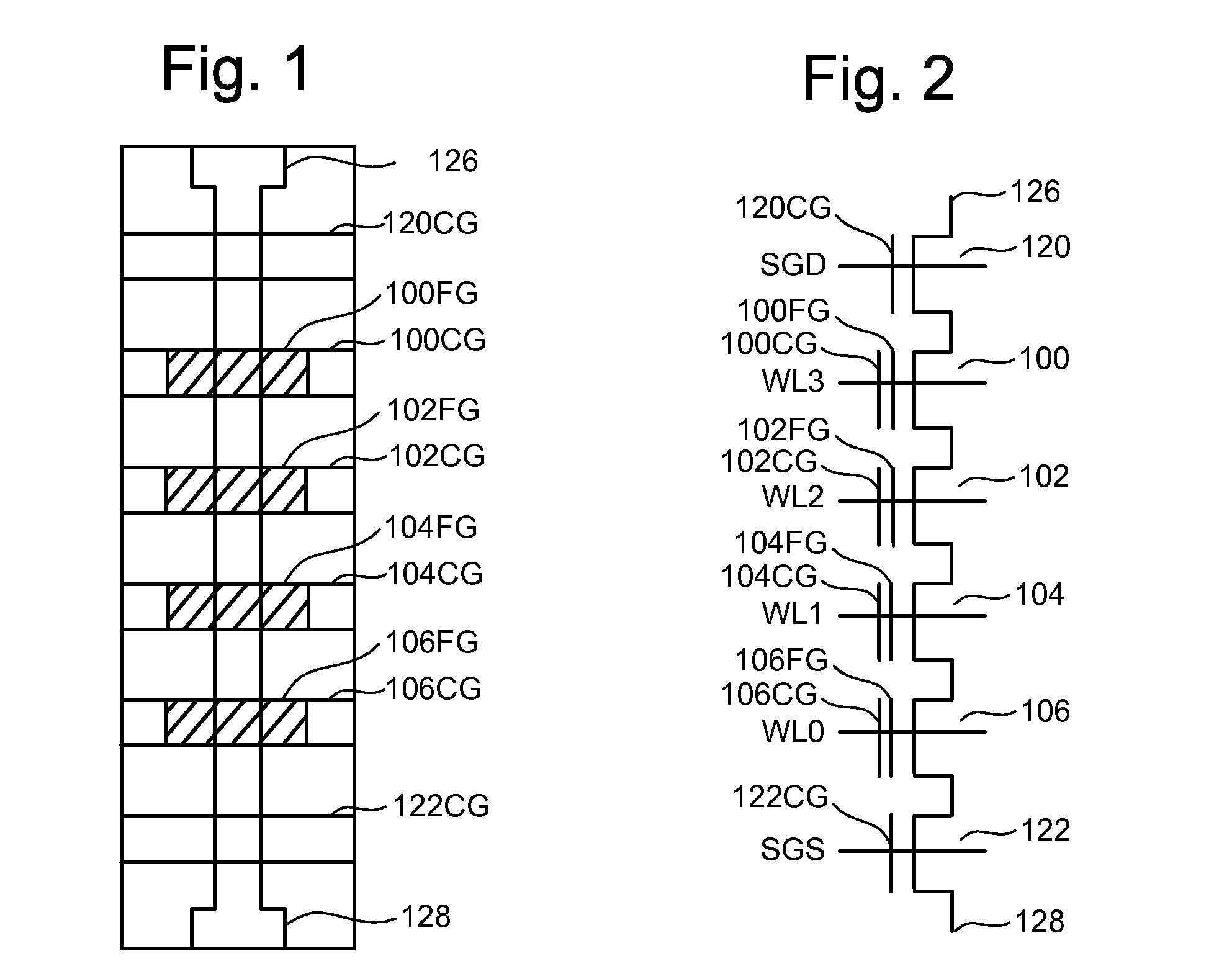
[0034]FIG. 1 is a top view showing one NAND string. FIG. 2 is an equivalent circuit thereof. Shielding and isolation techniques in accordance with embodiments are presented with respect to nonvolatile flash memory, specifically NAND type flash memory, for purposes of explanation. It will be appreciated by those of ordinary skill in the art, however, that the techniques set forth are not so limited and can be utilized in many fabrication processes to fabricate various types of integrated circuits. For example, these techniques can be used to fabricate NOR type memories or other devices where shielding is needed between neighboring charge storage regions.

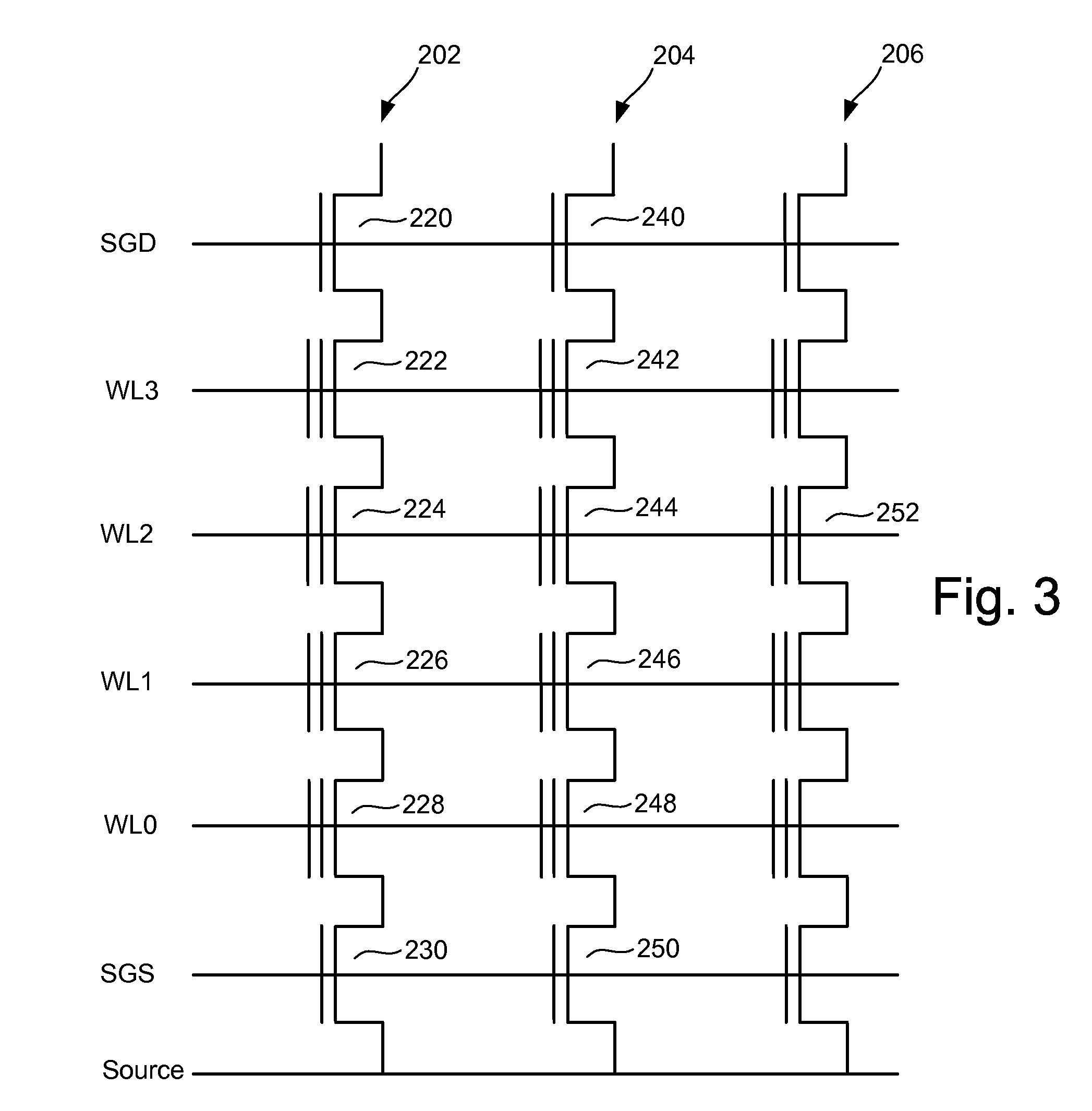
[0035]The NAND string depicted in FIGS. 1 and 2 includes four transistors 100, 102, 104 and 106 in series and sandwiched between a first select gate 120 and a second select gate 122. Select gate 120 connects the NAND string to a bit line via bit line contact 126. Select gate 122 connects the NAND string to a common source line via sou...


PUM


Abstract

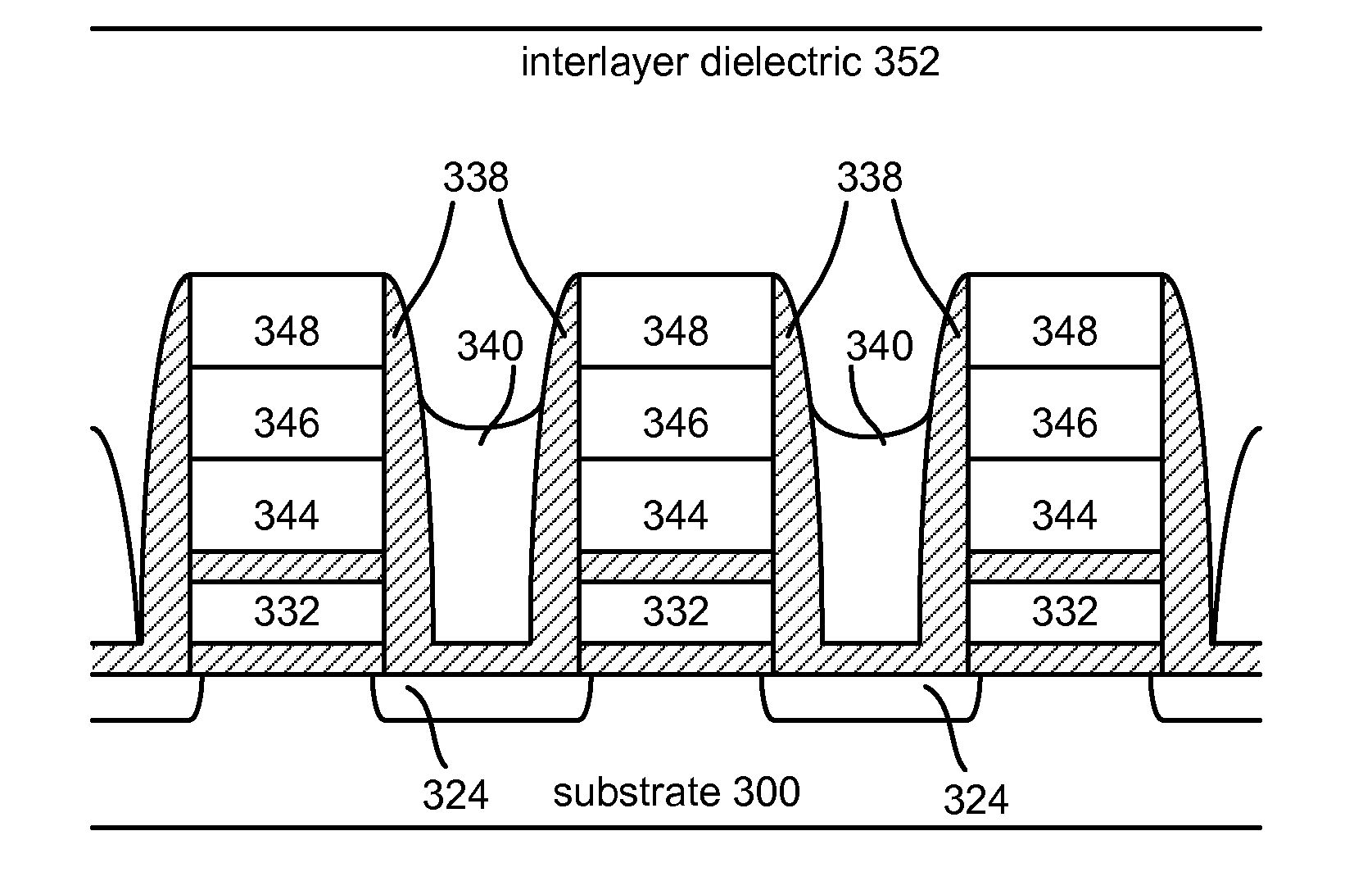
Shield plates for reduced coupling between charge storage regions in nonvolatile semiconductor memory devices, and associated techniques for forming the same, are provided. Electrical fields associated with charge stored in the floating gates or other charge storage regions of a memory device can couple to neighboring charge storage regions because of the close, and continually decreasing proximity of these regions. A shield plate can be formed adjacent to the bit line sides of floating gates that face opposing bit line sides of adjacent floating gates. Insulating layers can be formed between each shield plate and its corresponding adjacent charge storage region. The insulating layers can extend to the levels of the upper surfaces of the control gates formed above the charge storage regions. In such a configuration, sidewall fabrication techniques can be implemented to form the insulating members and shield plates. Each shield plate can be deposited and etched without complex masking to connect the control gates and shield plates. In one embodiment, the shield plates are at a floating potential.

Description

CROSS-REFERENCE TO RELATED APPLICATION[0001]The following application is cross-referenced and incorporated by reference herein in its entirety:[0002]U.S. patent application No. ______ [Attorney Docket No. SAND-01079US0], entitled “Methods of Fabricating Shield Plates for Reduced Field Coupling in Non-Volatile Memory,” by Jack H. Yuan, filed on even date herewith.BACKGROUND OF THE INVENTION[0003]1. Field of the Invention[0004]Embodiments of the present disclosure are directed to high density semiconductor devices, such as nonvolatile memory, and systems and methods for isolating components in high density semiconductor devices.[0005]2. Description of the Related Art[0006]Semiconductor memory devices have become more popular for use in various electronic devices. For example, nonvolatile semiconductor memory is used in cellular telephones, digital cameras, personal digital assistants, mobile computing devices, non-mobile computing devices and other devices. Electrical Erasable Program...

Claims


Application Information

Patent Timeline
IPC IPC(8): H01L29/788
CPCG11C16/3418H01L27/11524H01L27/11521H01L27/115H10B41/35H10B69/00H10B41/30
Inventor YUAN, JACK H.
Owner SANDISK TECH LLC
Learn More