MEMS microphone module and method thereof

a microphone module and microphone technology, applied in the field ofmems microphone modules, can solve the problems of increasing the difficulty of achieving a miniaturized microphone module, reducing the transmission speed of the device, and increasing the overall fabrication cost, so as to reduce the overall operation time, reduce the package size, and increase the reliability of the package significantly.

Active Publication Date: 2008-07-03
ADVANCED SEMICON ENG INC
View PDF6 Cites 82 Cited by
  • Summary
  • Abstract
  • Description
  • Claims
  • Application Information

AI Technical Summary

Benefits of technology

[0006]A MEMS microphone module having an application specific IC and a microphone chip is disclosed. The application specific IC has a plurality of first vias and a plurality of first pads, and the first vias are connected to the first pads. The microphone chip has a resonant cavity, a plurality of second vias and a plurality of second pads, in which the second vias are connected to the second pads. The microphone chip is disposed on a first surface of the application specific IC with an opening of the resonant cavity facing toward a first surface of the application specific IC. The sec

Problems solved by technology

Unfortunately, the utilization of bonding wires often creates a longer path for signal transmission and reduces the transmission speed for the device, and the prolonged fabrication time for this type of modules also increas

Method used


Image

  • MEMS microphone module and method thereof
  • MEMS microphone module and method thereof
  • MEMS microphone module and method thereof

Examples


Embodiment Construction

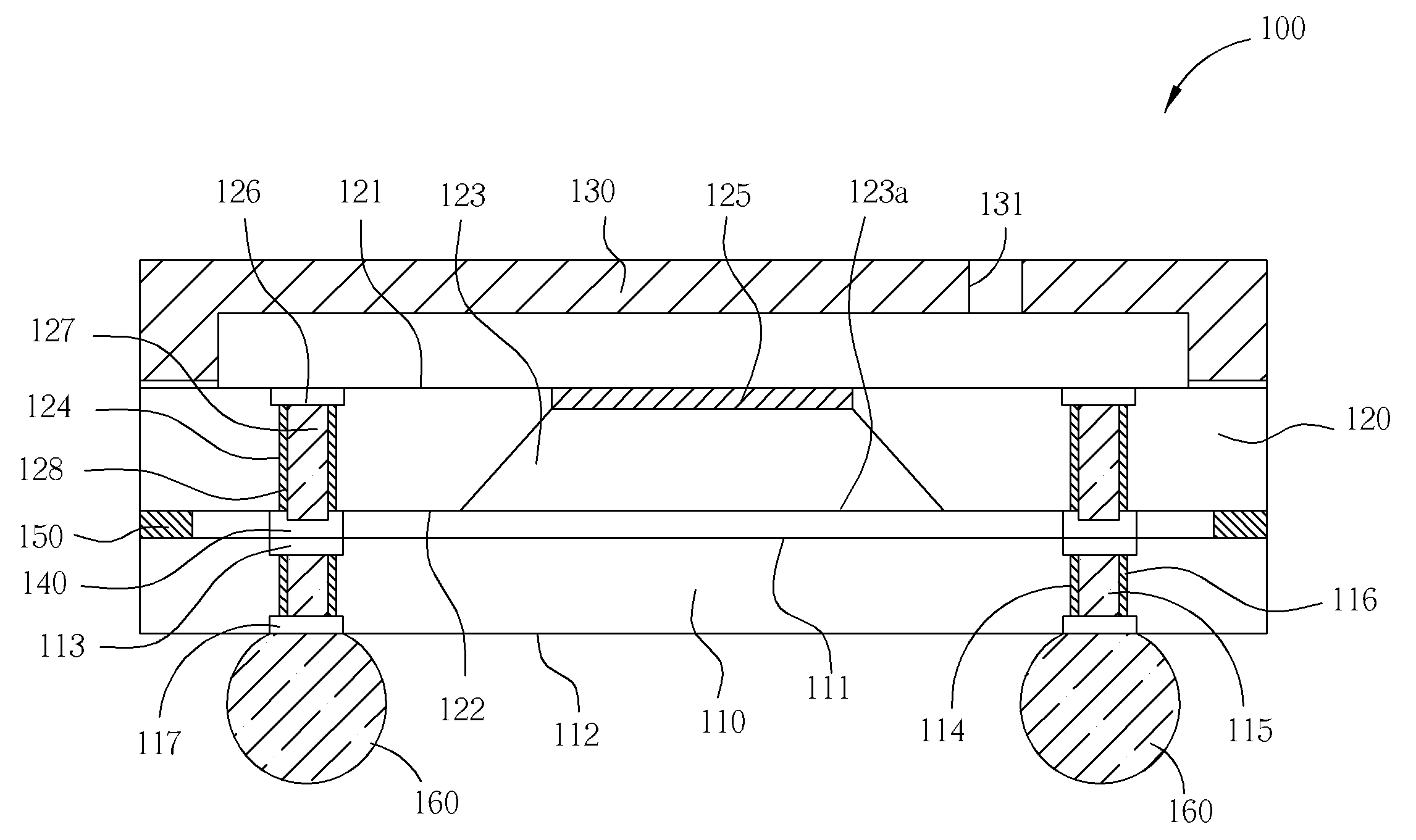
[0012]Referring to FIG. 1, FIG. 1 illustrates a MEMS microphone module 100 according to a first embodiment of the present invention. The MEMS microphone module 100 includes an application specific IC 110, a microphone chip 120, and a cover 130. The application specific IC 110 has a first surface 111, a second surface 112, a plurality of first pads 113, and a plurality of first vias 114. The first pads 113 are formed on the first surface 111 of the application specific IC 110, and the first vias 114 connected to the first pads 113 are formed to communicate with the first surface 111 and the second surface 112.

[0013]The microphone chip 120 has an active surface 121, a back surface 122, a resonant cavity 123, a plurality of second vias 124, a vibrating film 125, and a plurality of second pads 126. The resonant cavity 123 and the second vias 124 are formed on the back surface 122 of the microphone chip 120, in which the resonant cavity 123 includes an opening 123a. The vibrating film 12...


PUM


Abstract

A MEMS microphone module having an application specific IC and a microphone chip is disclosed. The application specific IC has a plurality of first vias and a plurality of first pads, and the first vias are connected to the first pads. The microphone chip has a resonant cavity, a plurality of second vias and a plurality of second pads, and the second vias are connected to the second pads. The microphone chip is disposed on a first surface of the application specific IC with an opening of the resonant cavity facing toward a first surface of the application specific IC. The second conductive vias of the microphone chip are also electrically connected to the first vias of the application specific IC. By placing the microphone chip on the first surface of the application specific IC, the present invention could reduce the package size and increase the reliability of the package.

Description

BACKGROUND OF THE INVENTION[0001]1. Field of the Invention[0002]The present invention relates to a MEMS microphone module, and more particularly, to a MEMS microphone module having a fabrication process capable of eliminating wire bonding and die bonding processes.[0003]2. Description of the Prior Art[0004]As fabrication for semiconductor devices and micro-electromechanical systems advances, the size and volume of microphone modules also proceeds toward a direction of miniaturization. In conventional packaging processes for a microphone module, microphone chips and signal conversion chips are placed on a substrate and bonding wires are formed to connect the microphone chip, the signal conversion chip, and the substrate. Unfortunately, the utilization of bonding wires often creates a longer path for signal transmission and reduces the transmission speed for the device, and the prolonged fabrication time for this type of modules also increases the overall fabrication cost. Typically, ...

Claims


Application Information

Patent Timeline
IPC IPC(8): H01L45/02H01L21/77
CPCB81C1/00238B81B2201/0257
Inventor HSIAO, WEI-MIN
Owner ADVANCED SEMICON ENG INC
Why Eureka
Try Eureka