Method and device for monitoring radio-frequency exposure in a magnetic resonance measurement
a magnetic resonance and radiofrequency exposure technology, applied in the direction of reradiation, measurement using nmr, instruments, etc., can solve the problems of high patient exposure, -frequency power, and system operation with overly large safety intervals
- Summary
- Abstract
- Description
- Claims
- Application Information
AI Technical Summary
Benefits of technology
Problems solved by technology
Method used
Image
Examples
Embodiment Construction
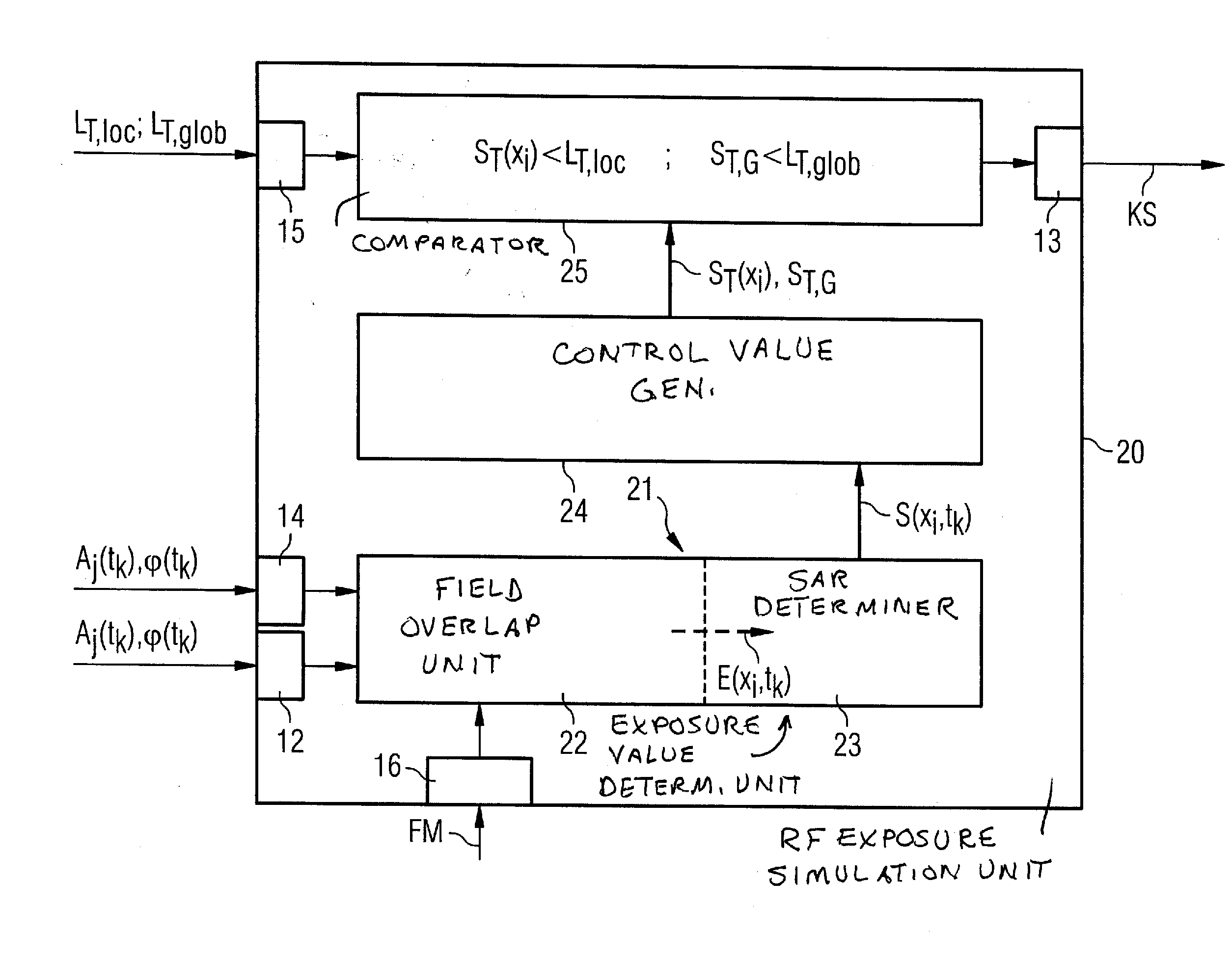
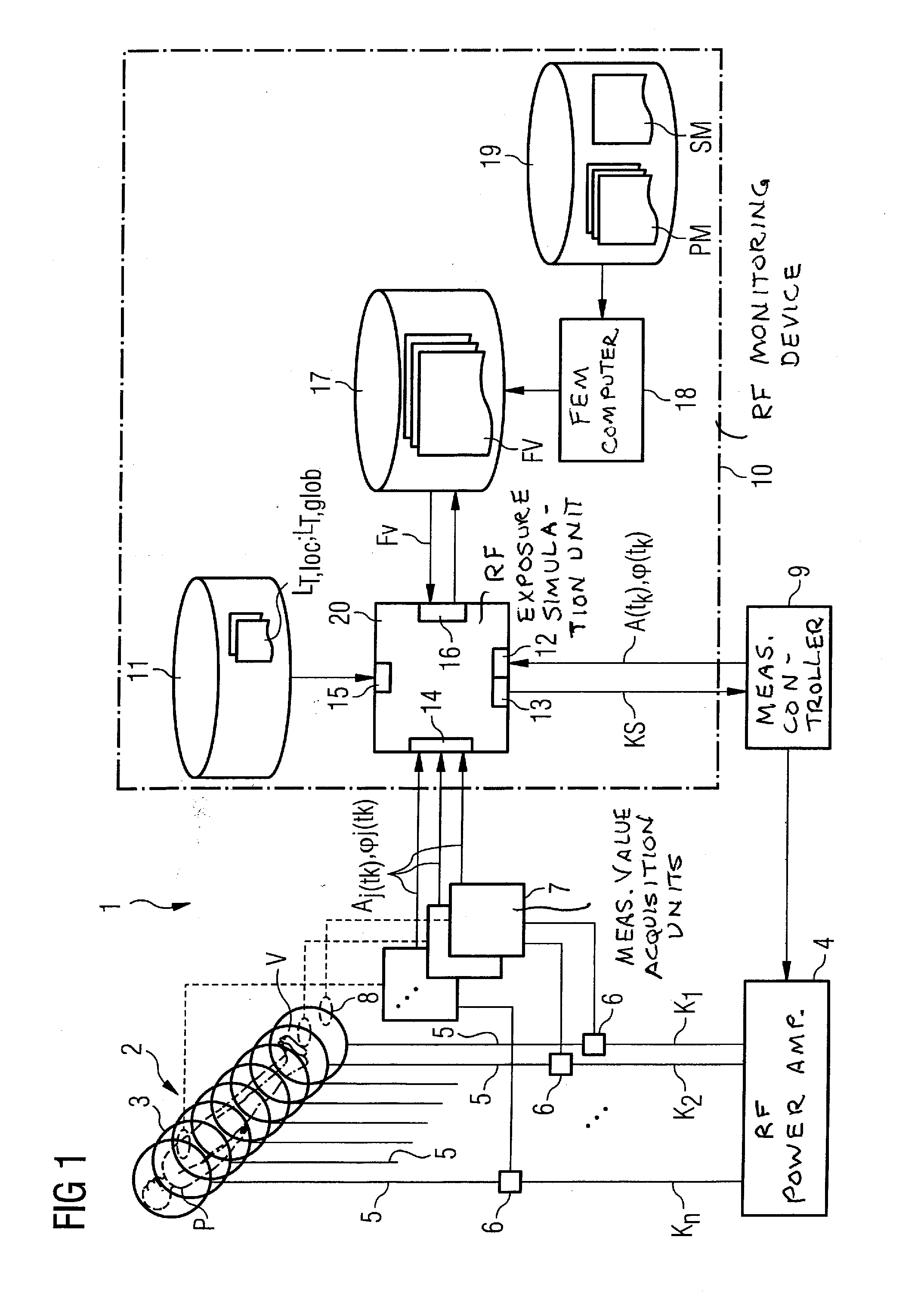
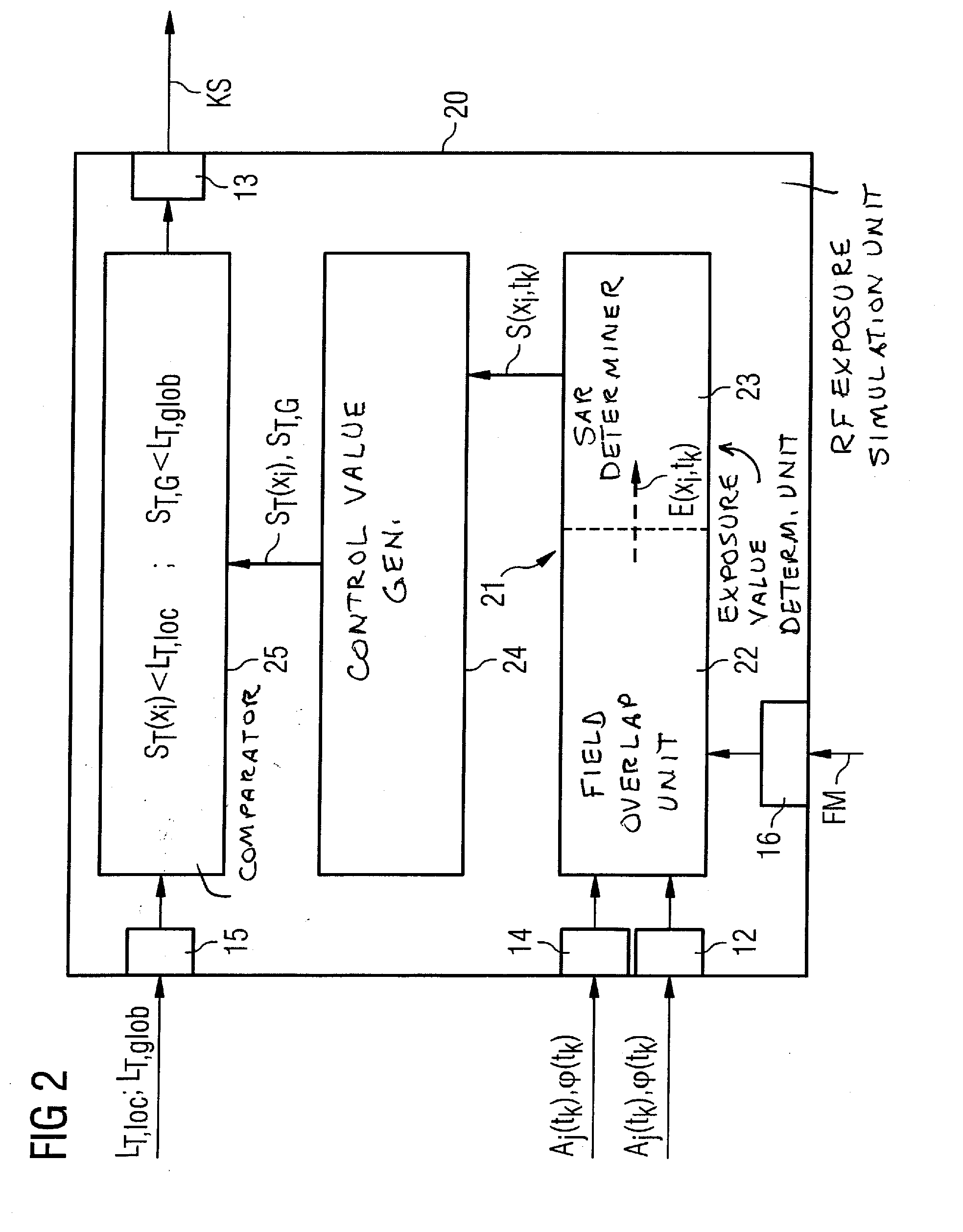
[0036]As an important component of a magnetic resonance system 1, FIG. 1 schematically shows an antenna structure 2 that encloses an examination volume V in which an examination subject P (here a patient P) is located. The antenna structure 2 includes a number of individual antenna elements 3 that are represented in FIG. 1 as individual annular coils, but the antenna structure can be fashioned differently. The antenna elements 3 are respectively connected via separate antenna feed lines 5 (also called feed lines) with a radio-frequency power amplifier 4 that delivers radio-frequency signals in a power range between 10 watts and 20 kW for the antenna elements 3. The individual antenna elements 3, together with their associated antenna feed lines 5, respectively form radio-frequency signal channels K1, K2, . . . , Kn (also called “transmission channels” in the following). Each transmission channel K1, K2, . . . , Kn is separately controlled by the radio-frequency power amplifier 4, me...
PUM
 Abstract
Description
Claims
Application Information
 - R&D
- Intellectual Property
- Life Sciences
- Materials
- Tech Scout
- Unparalleled Data Quality
- Higher Quality Content
- 60% Fewer Hallucinations
Browse by: Latest US Patents, China's latest patents, Technical Efficacy Thesaurus, Application Domain, Technology Topic, Popular Technical Reports.
© 2025 PatSnap. All rights reserved.Legal|Privacy policy|Modern Slavery Act Transparency Statement|Sitemap|About US| Contact US: help@patsnap.com


