Noise reduction within an electronic device using automatic frequency modulation

a technology of automatic frequency modulation and electronic devices, applied in the direction of generating/distributing signals, pulse techniques, instruments, etc., can solve the problems of not providing a signal with a precise and predictable frequency and phase, the use of crystals adds significant costs to the system not, and the majority of circuit based oscillators suffer

Active Publication Date: 2008-07-03
APPLE INC
View PDF35 Cites 186 Cited by
  • Summary
  • Abstract
  • Description
  • Claims
  • Application Information

AI Technical Summary

Benefits of technology

[0009]The operation of the frequency sensitive element can depend on the frequency of the oscillating signal. The controller can receive a control input signal from the frequency sensitive element. The control input signal can indicate the operation of the frequency sensitive element and can thus be dependent on the frequency of the oscillating signal.
[0010]The controller can modify the frequency of the oscillating signal by causing the reference generator to output reference signals of varying magnitude. While modifying the frequency, the controller can monitor the control input and note at which frequencies the frequency sensitive element operates as desired. The controller can then find a desired frequency in which the frequency sensitive element operates as desired and controls the reference generator in order to keep the oscillating signal at the desired frequency.
[0011]In additional embodiments, the controller can perform additional scanning and mathematical operations in order to find an optimal frequency. Furthermore, the controller can monitor the control input signal continuously and if, for any reason, the frequency sensitive element stops operating in a desired manner, modify the frequency as necessary.

Problems solved by technology

However, most circuit based oscillators suffer from the fact that they do not provide a signal with a precise and predictable frequency and phase.
However, the use of crystals adds significant costs to the system not only because of the crystal itself but also because of associated support circuitry and PCB space., which is usually very limited in some devices such as, for example, small hand held products.

Method used


Image

  • Noise reduction within an electronic device using automatic frequency modulation
  • Noise reduction within an electronic device using automatic frequency modulation
  • Noise reduction within an electronic device using automatic frequency modulation

Examples


Embodiment Construction

[0030]In the following description of preferred embodiments, reference is made to the accompanying drawings which form a part hereof, and in which it is shown by way of illustration specific embodiments in which the invention can be practiced. It is to be understood that other embodiments can be used and structural changes can be made without departing from the scope of the preferred embodiments of the present invention.

[0031]Although embodiments of the present invention may be described herein in the context of a touch sensitive panel, it should be understood that the present invention is not limited to touch sensitive panels, but is generally applicable to other electronic circuits requiring a precise oscillating signal.

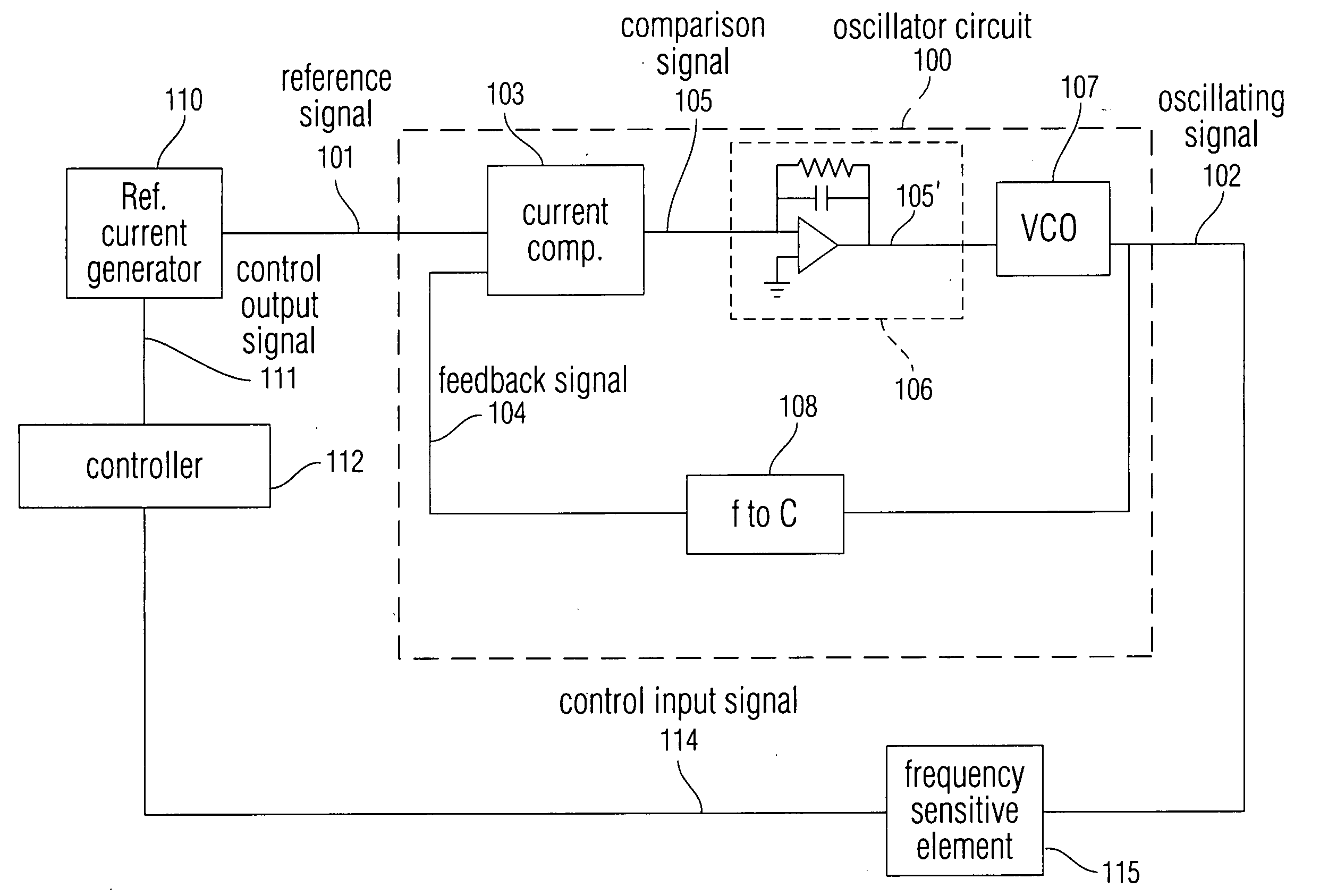
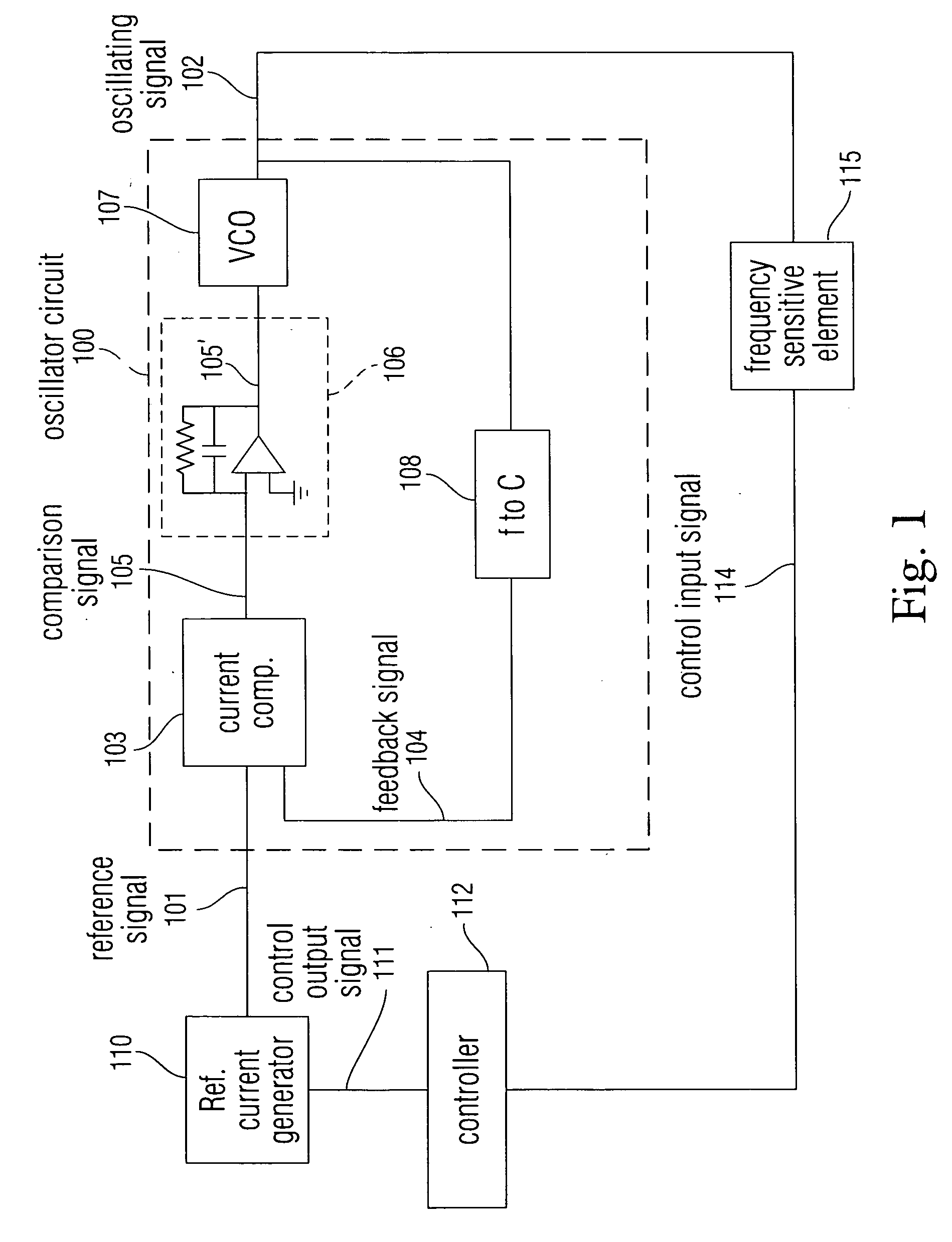
[0032]An oscillating signal which does not rely on a crystal to provide a reference signal is disclosed. Instead, circuit based elements can be used to generate an oscillating signal, while a controller can monitor the effect the oscillating signal is having on one...


PUM


Abstract

Disclosed is a system and method for providing an oscillating signal of relatively precise frequency without using a signal provided by a crystal as a reference. Disclosed is a feedback oscillator circuit configured to output an oscillating signal having a frequency defined by a reference signal. The oscillating signal can be sent to one or more circuits including at least one frequency sensitive element. The frequency sensitive element produces an output signal which depends on the frequency of the oscillating signal. A controller controls the reference signal in order to cause an attribute of the output signal to have a value within a desired range.

Description

FIELD OF THE INVENTION [0001]This invention relates to tuned oscillation circuits for electronic devices, and more particularly to providing a precise oscillating signal without using a crystal as a reference.BACKGROUND OF THE INVENTION [0002]Oscillating signals are widely used in electronics. Examples of their use include providing clock signals, or providing carrier signals which can later be modified to include information. For example, an oscillating signal can be used to drive a row in a capacitive touch sensor panel. Changes to the sensed signal indicate a touch event at the panel.[0003]There are various known ways to create an oscillating signal. For example, persons of skill in the art would recognize that a simple circuit including an inductor and a capacitor would create such a signal. However, most circuit based oscillators suffer from the fact that they do not provide a signal with a precise and predictable frequency and phase.[0004]Therefore, many electronic devices use...

Claims


Application Information

Patent Timeline
Patent Type & Authority Applications(United States)
IPC IPC(8): H03L7/00G06F1/04G06F3/041
CPCG06F3/0418H03L7/097G06F3/044G06F3/0446
Inventor KRAH, CHRISTOPH HORST
Owner APPLE INC
Why Eureka
Try Eureka