Backlight unit and liquid crystal display device using the backlight unit

a liquid crystal display device and backlight technology, applied in static indicating devices, lighting and heating apparatuses, instruments, etc., can solve the problems of not being able to achieve three-dimensional image rendering capability, unable to provide stereoscopic feeling with images rendered on a planar screen,

Inactive Publication Date: 2008-07-03
SHARP KK
View PDF4 Cites 12 Cited by
  • Summary
  • Abstract
  • Description
  • Claims
  • Application Information

AI Technical Summary

Problems solved by technology

On the other hand, for rendering images with further reality, there still remains an issue on how to provide stereoscopic feeling with the images rendered on a planar screen.
For example, with a so-called hold-on display type display device which is represented by a liquid crystal display providing a liquid crystal panel with light having uniform brightness on a screen, three-dimensional image rendering capability is not sufficient.
That is, in order to output an image with stereoscopic effect and perspective, a method to provide suitable distribution in brightness of the object to be recreated may be a solution, however, complexity of image signal processing has prevented the technology from being progressed.
As described above, representation of stereoscopic effect and feeling of presence is not sufficient with a conventional hold-on display type display device compared with a display device using a cathode-ray tube, as the brightness distribution is uniform over the whole screen.
If the brightness of the peripheral portion of the screen excluding the gazing point is equals to or higher than the brightness of the central portion which is the gazing point, a man is bothered by visually uncomfortable feeling, and becomes tired easily.
However, uneven brightness is easily caused between the portions where light sources are disposed and the other portions where light sources are not disposed.
The display device using the edge light type backlight unit can reduce the thickness, however, the mass of the light guiding body becomes excessively large with a large model, and the brightness on the screen becomes difficult to be attained as the screen gets larger.
However, the backlight units do not implement two-dimensional characteristics in accordance with visual sense characteristics of a man as provided by a display device using a cathode-ray tube, that is, brightness distribution characteristics with gradient being formed at least in the horizontal and vertical directions from the central portion of a screen.
Therefore issues of visual uncomfortableness and fatigability for a man have not been improved yet.

Method used


Image

  • Backlight unit and liquid crystal display device using the backlight unit
  • Backlight unit and liquid crystal display device using the backlight unit
  • Backlight unit and liquid crystal display device using the backlight unit

Examples


embodiment 1

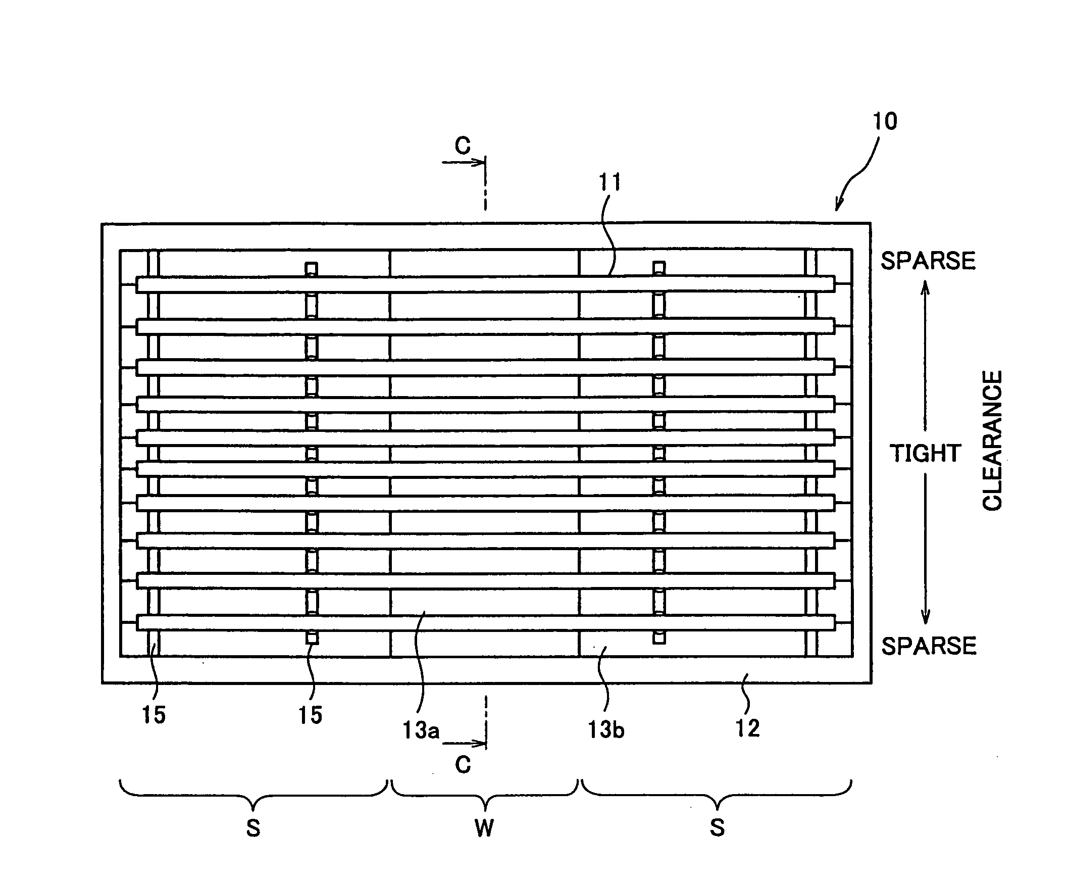
[0095]In this embodiment, brightness gradient forming means to form brightness gradient at least in the horizontal and vertical directions on the display screen (the liquid crystal panel) is provided for a reflection layer disposed in a backlight unit, so that the brightness at the central portion of the screen and in the vicinity thereof is relatively higher than the brightness at the peripheral portion of the screen, just like a display device using a cathode-ray tube. This brightness gradient forming means in this embodiment is provided for the purpose of controlling reflectance of the light from a light source.

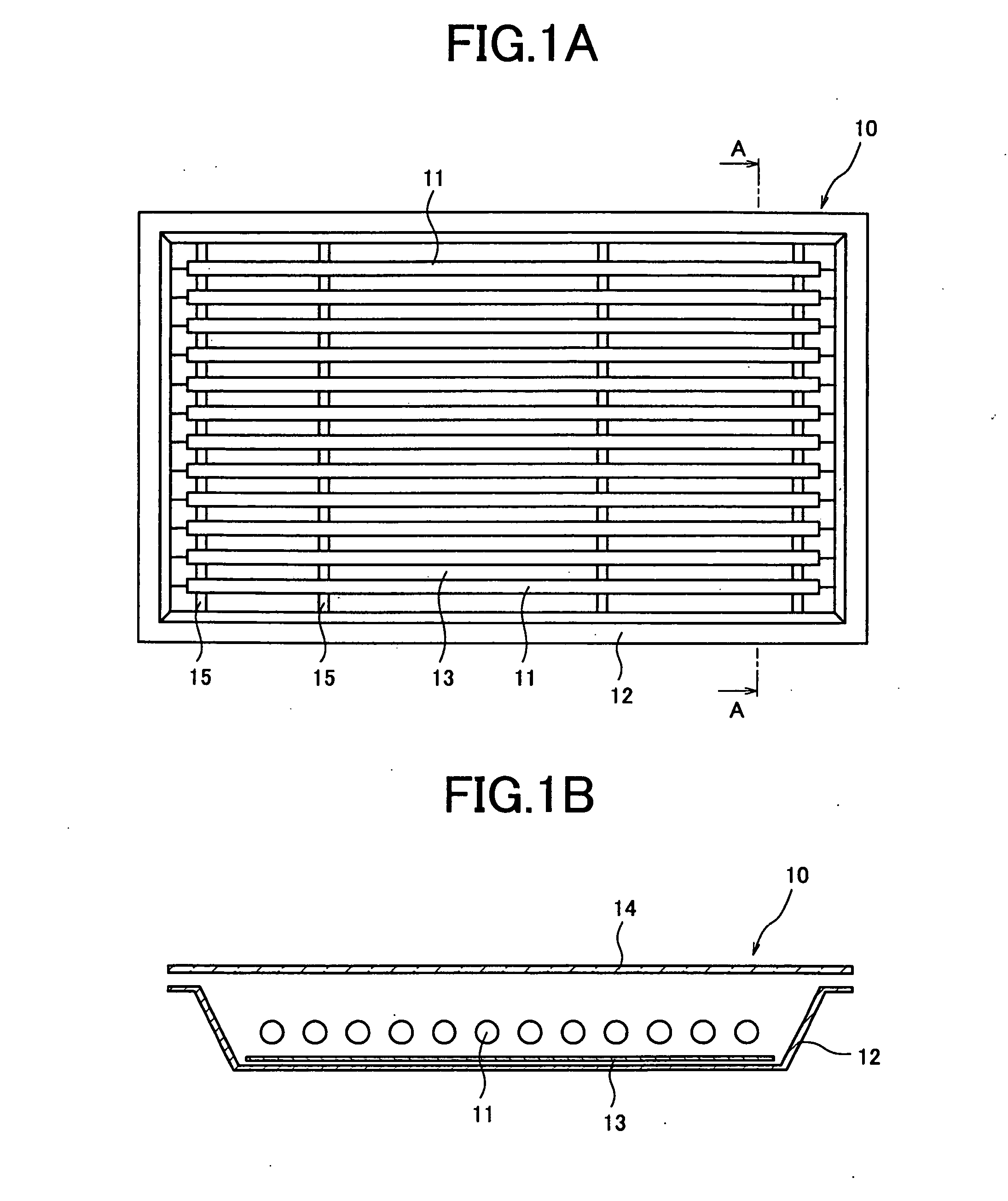
[0096]FIGS. 1A and 1B are the drawings for explaining an embodiment of a direct-lighting backlight unit of the present invention. A schematic plan view showing the internal structure of the backlight unit is shown in FIG. 1A while a schematic structural view of the backlight unit, illustrating cross-section A-A of FIG. 1A is shown in FIG. 1B. In FIGS. 1A and 1B, reference ...

embodiment 2

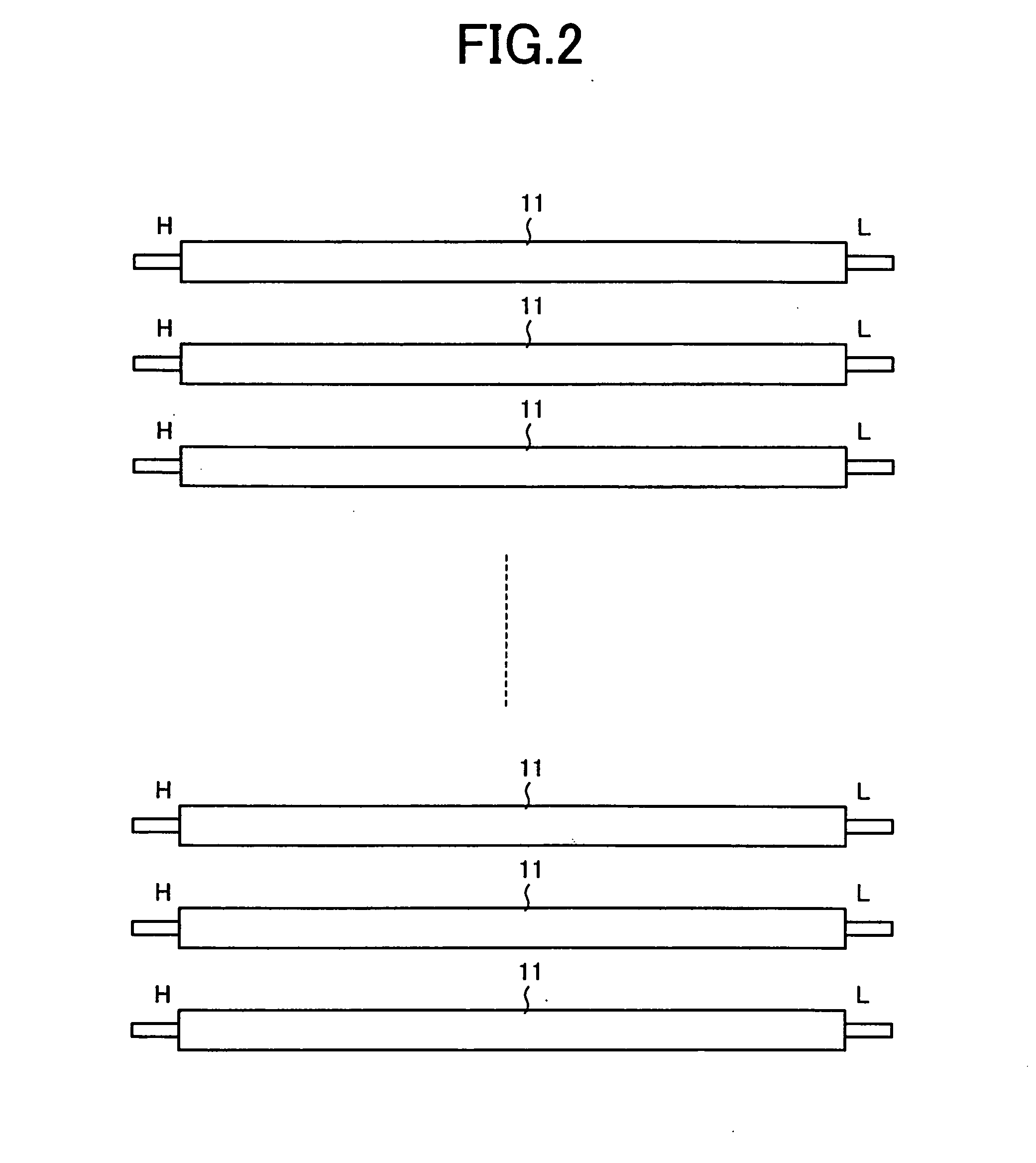
[0116]FIG. 5 is a drawing showing another embodiment of the backlight unit of the present invention, which is a cross-sectional schematic view equivalent to section A-A of the backlight unit shown in FIG. 1A. As a reflection unit, the backlight unit of this embodiment has a reflection surface 12a, instead of a reflection layer 13 of aforementioned Embodiment 1, to reflect the light from fluorescent lamps 11 toward a diffusion unit 14. The reflection surface 12a is formed by a reflecting film made of a high reflectance material such as silver or aluminum formed on the inner surface of the bottom of the enclosure 12. As shown in FIG. 2, fluorescent lamps 11 are arranged so that high voltage side H and low voltage side L of each of the fluorescent lamps are aligned respectively to the same sides.

[0117]In this embodiment, the brightness gradient forming means for controlling light reflectance as described in Embodiment 1 above is disposed on the reflection surface 12a. FIG. 6 is a drawi...

embodiment 3

[0118]FIG. 7 is a drawing for explaining another structural example of the backlight unit of the present invention, showing a schematic cross-sectional view equivalent to section A-A of the backlight unit shown in FIG. 1A. As a reflection unit, the backlight unit of this embodiment has a reflection layer 13 shown in the structure in FIGS. 1A and 1B and a reflection surface 12a shown in FIG. 5. As shown in FIG. 2, fluorescent lamps 11 are arranged so that high voltage side H and low voltage side L of each of the fluorescent lamps are aligned respectively to the same sides.

[0119]As described in Embodiment 1, a reflection layer 13 is disposed on an enclosure 12 of a backlight unit 10. For the reflection layer 13, for example, aforementioned foamed PET sheet is used, providing a reflection function to reflect the light from fluorescent lamps 11, however part of the light transmits the reflection layer 13 and exits to the rear side thereof. On the inner surface of the bottom of the backl...


PUM

PropertyMeasurementUnit
brightnessaaaaaaaaaa
radiation brightnessaaaaaaaaaa
sizesaaaaaaaaaa

Abstract

A backlight unit includes a fluorescent lamp to illuminate a liquid crystal panel, a reflection unit for causing the light from the fluorescent lamp to exit toward a certain direction, and a diffusion unit for diffusing the light from the fluorescent lamp and reflection unit, and reflectance or transmittance in the horizontal and vertical directions is controlled by applying a dot pattern that gradually increases densities from the central portion toward the peripheral portion to the reflection unit or diffusion unit, or by applying a dot pattern that gradually increases densities from the central portion toward the both ends in the longitudinal direction on the surface of the fluorescent tube of the fluorescent lamp. By doing this, brightness gradient is formed in the horizontal and vertical directions so that the brightness in the central portion of the liquid crystal panel is relatively higher than the brightness of the peripheral portion thereof.

Description

[0001]This application is a Divisional of co-pending application Ser. No. 10 / 531,919 filed on Nov. 10, 2005, which claims priority on Japanese Application No. PCT / JP03 / 13357 filed on Oct. 17, 2003. The entire contents is hereby incorporated by reference.TECHNICAL FIELD[0002]The present invention relates to a backlight unit for lighting an object from the rear side, and to a liquid crystal display device using the backlight unit.BACKGROUND OF THE INVENTION[0003]High image rendering capabilities have been demanded for a display device represented by a television set and projector device. Especially, optimized design of a display device has been studied to implement technological means that provides a viewer with the feelings of presence and immersion. To implement these feelings of presence and immersion, standardizations have been progressed through optimization of the relationship between viewing angle characteristics of a man and display screen sizes. That is, attempts have been ma...

Claims


Application Information

Patent Timeline
Patent Type & Authority Applications(United States)
IPC IPC(8): B60Q1/26G02F1/01G02F1/13357G09G3/36
CPCG02F1/133603G02F1/133605G09G2320/0626G09G2310/0232G09G2320/0276G09G3/3611
Inventor INOUE, YUTAKAOHTSUKA, KOHJIIZUMI, KAZUYOSHIYOSHII, TAKASHI
Owner SHARP KK
Why Eureka
Try Eureka