Method for determining the rotation speed of rotating shaft

a technology of rotating shaft and rotation speed, which is applied in the direction of time traversed devices, instruments, horology, etc., can solve the problems of increasing the demand for this type of signal transfer system, increasing the number of sensors, and increasing the number of clock cycles. achieve the effect of increasing the measurement accuracy of the sensor

Inactive Publication Date: 2008-07-03
ROBERT BOSCH GMBH
View PDF8 Cites 18 Cited by
  • Summary
  • Abstract
  • Description
  • Claims
  • Application Information

AI Technical Summary

Benefits of technology

[0005]An object of the present invention is therefore to increase the measurement accuracy of a sensor that can transfer rotation-speed or angle information in coded fashion.

Problems solved by technology

As the rotation speed increases, the demands on this type of signal transfer system increase.
One problem with such methods for data transfer is that only a relatively inaccurate clock cycle is available in the sensor.
Whereas a relatively complex control unit usually contains a quartz oscillator, in a sensor only a relatively inaccurate electronic circuit is present in order to generate a clock cycle.

Method used


Image

  • Method for determining the rotation speed of rotating shaft
  • Method for determining the rotation speed of rotating shaft
  • Method for determining the rotation speed of rotating shaft

Examples


Embodiment Construction

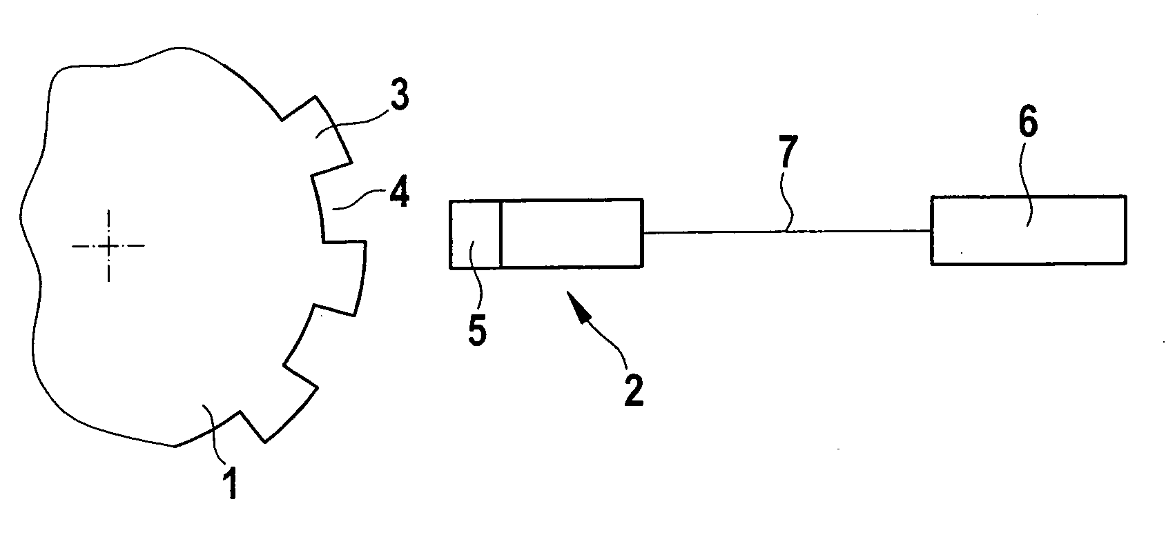
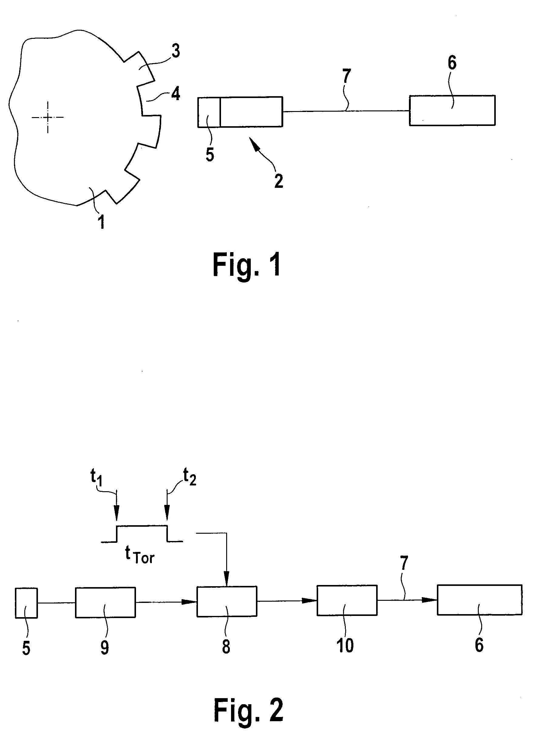
[0013]FIG. 1 shows an assemblage of a sensor wheel 1 and a sensor 2. Sensor wheel 1 is joined to a crankshaft (not depicted) of an internal combustion engine, so that sensor wheel 1 co-rotates with the crankshaft. Sensor wheel 1 encompasses markings, for example in the form of an alternating pattern of teeth 3 and tooth gaps 4. As the markings are carried past sensor 2, the markings trigger electrical signals of a sensor element 5. Sensor element 5 can be, for example, a Hall sensor, an inductive sensor, or the like, so that the electrical signal of sensor element 5 is a square-wave voltage that corresponds to a development of the sequence of teeth 3 and tooth gaps 4 of sensor wheel 1. Teeth 3 and tooth gaps 4 generate two different states in sensor 2. These states are transferred to an electronic control unit 6, for example as a pulse train having two levels of an electrical voltage (square-wave voltage) or of an electrical current. Data transfer between sensor 2 and control unit 6...


PUM


Abstract

A method for determining the rotation speed of a rotating shaft that has associated with it a means that has markings which produce an electrical signal upon being carried past a sensor element of a sensor, the sensor encompassing an evaluation device that counts the markings carried past the sensor element within a gate time and transfers them to a control unit as a numerical value. The gate time is derived from a time increment, and a pulse having an actual time duration derived from the time increment is transferred to the control unit and is compared by the control unit with a target time duration, the numerical value being corrected using a correction value that is ascertained from a comparison of the actual time duration with the target time duration.

Description

FIELD OF THE INVENTION[0001]The present invention relates to a method and an assemblage for determining the rotation speed of a rotating shaft that has associated with it a means that has markings which produce an electrical signal upon being carried past a sensor element of a sensor, the sensor encompassing an evaluation device that counts the markings carried past a sensor element within a gate time and transfers them to a control unit as a numerical value. The present invention further relates to a sensor for an assemblage of this kind, as well as a computer program for carrying out the method.BACKGROUND INFORMATION[0002]In the related art, the rotation speed of a rotating shaft is measured, for example, by measuring markings of a sensor wheel that is carried past a sensor as the shaft rotates, and there generates electrical signals associated with increments of the rotary motion of the shaft. It is usual in the case of crankshafts, for example, to dispose a sensor wheel having t...

Claims


Application Information

Patent Timeline
Patent Type & Authority Applications(United States)
IPC IPC(8): G01P3/64
CPCG01P3/489G01P3/481
Inventor KASSNER, UWE
Owner ROBERT BOSCH GMBH
Why Eureka
Try Eureka