

To rotorcraft rotors fitted with inter-blade dampers
- Summary
- Abstract
- Description
- Claims
- Application Information
AI Technical Summary
Benefits of technology
Problems solved by technology
Method used
Image

Examples
Embodiment Construction
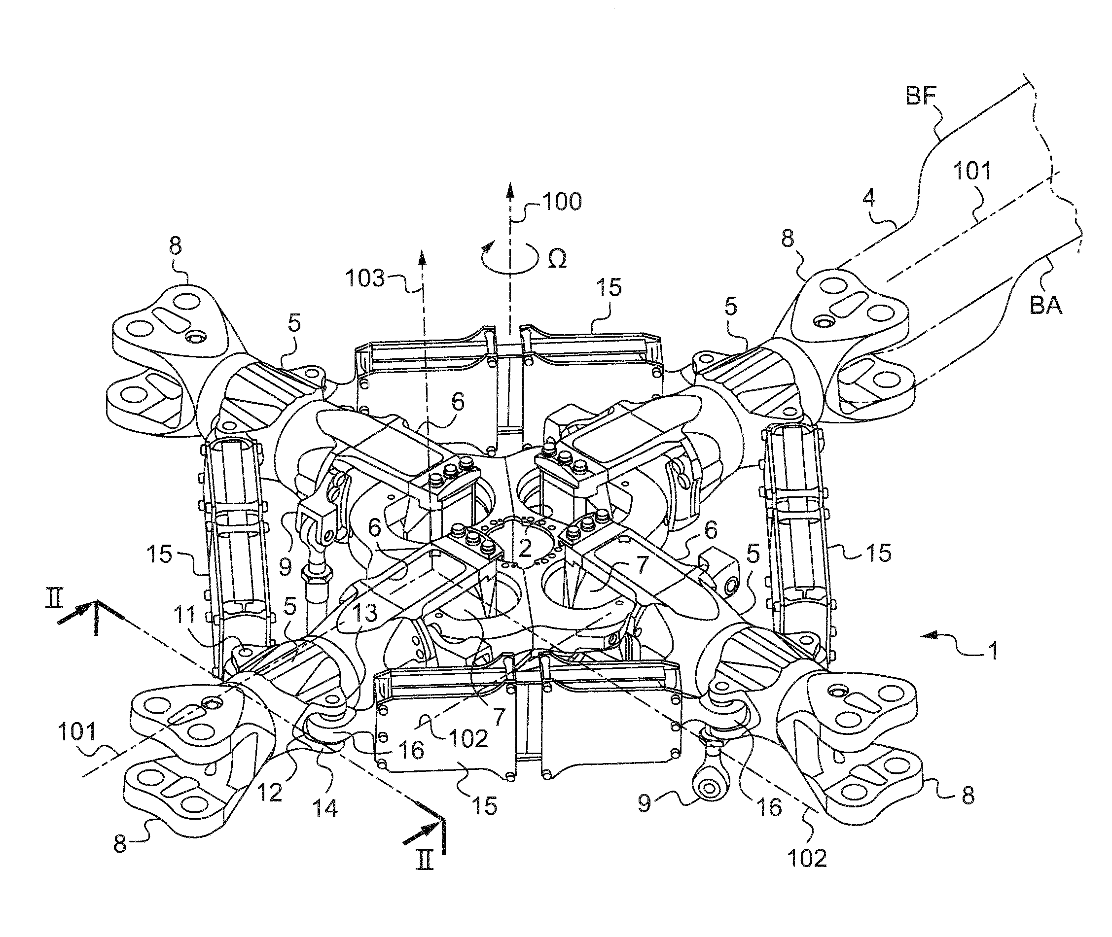
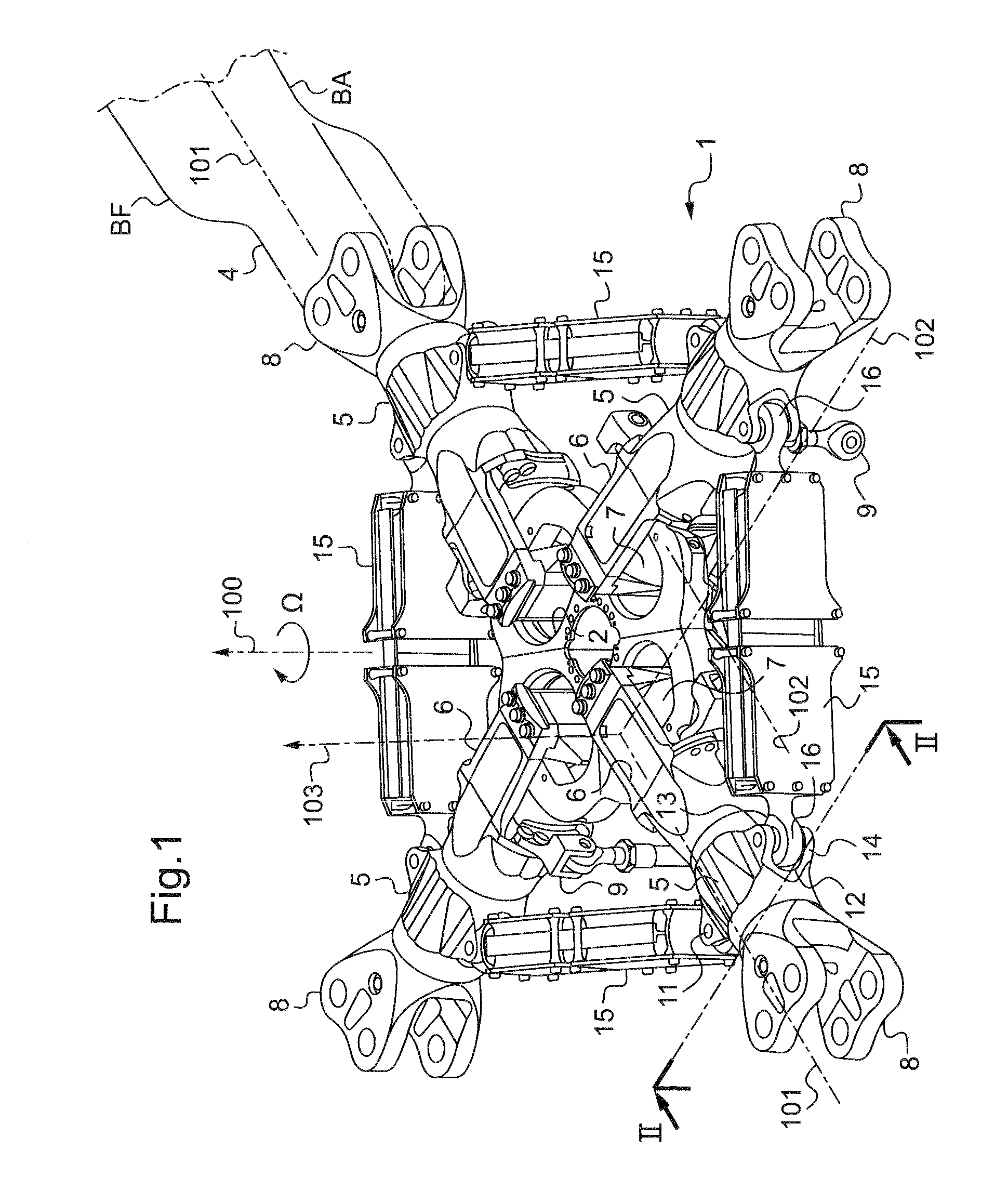
[0059]FIG. 1 shows a portion of a four-blade rotor head 1 of a rotorcraft having a rigid hub 2 constrained to rotate with a rotor mast (not shown) about an axis of rotation 100, with the speed of rotation of the hub 2 being referenced Ω.
[0060]The rotor mast is secured to a main power transmission gearbox (MGB) and transmits lift from the rotor to the structure of the rotorcraft and supports the blades 4 that transform the mechanical energy from the engines into aerodynamic forces.
[0061]Thus, the hub 2 serves as an attachment point for each of the blades 4 via a respective sleeve 5 having an inner radial yoke 6 fitted with a laminated spherical joint 7 (or spherical abutment) connecting it to the hub 2, and with an outer radial yoke 8 or fitting for retaining the corresponding blade 4.
[0062]Under such conditions, each laminated spherical joint 7 allows each corresponding blade 4 to move in vertical flapping about an axis 102 for vertical flapping, in drag, and also in pitch variation...
PUM
 Abstract
Description
Claims
Application Information