Method and System of Operating Molten Carbonate Fuel Cells

a fuel cell and carbonate technology, applied in the field of fuel cells, can solve the problems of low electromotive force of unit cells, no practical use, and change of porous structur

Inactive Publication Date: 2008-07-03
PARODI FILIPPO +2
View PDF3 Cites 38 Cited by
  • Summary
  • Abstract
  • Description
  • Claims
  • Application Information

AI Technical Summary

Benefits of technology

[0020]For these reasons, the present invention discloses a method, which allows verification of the chemical, physical and electrical conditions of every cell either in the design or in the working phase, based on the MCFC reference para

Problems solved by technology

A single cell forming the unit cell generates a low electromotive force of about 1 V, and is of no practical use.
Specifically, there are some situations: change of the porous structure and evaporation of the liquid electrolyte, which are due to the high temperature; consumption of the electrolyte and deterioration of the separator plates, which are due to the increased corrosion of the metal separator plate; and leakage of the fuel gas, due to these causes.
However, since the oversupply of the oxidant for suppressing the production of the hot section causes an overpressure within the cathodic passage, the oxidant gas can leak out due to the rupture of the wet seal or cross the matrices, thereby significantly shortening the life of the fuel cell body.
With high current values or when high fraction of the fuel is consumed by electrochemical reactions (the so-called “fuel utilisation factor”) some problems

Method used


Image

  • Method and System of Operating Molten Carbonate Fuel Cells
  • Method and System of Operating Molten Carbonate Fuel Cells
  • Method and System of Operating Molten Carbonate Fuel Cells

Examples


Embodiment Construction

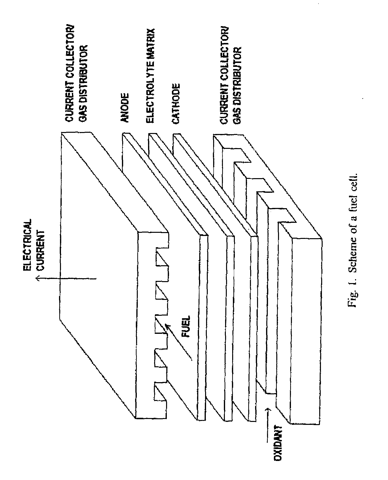
[0039]Molten carbonate fuel cells are reactors which, from an electrochemical point of view, have to be considered innovative since they convert the chemical energy of the fuel fed to the reactor directly into electrical energy. They are also characterised by high yields optimisation of the MCFC three steps have been used:

1. the evaluation of the experimental values of the MCFC which has to be tested;

2. the evaluation of the local chemical, physical and electrical conditions; the optimisation of the working conditions based on the results obtained and on specific operating constants.

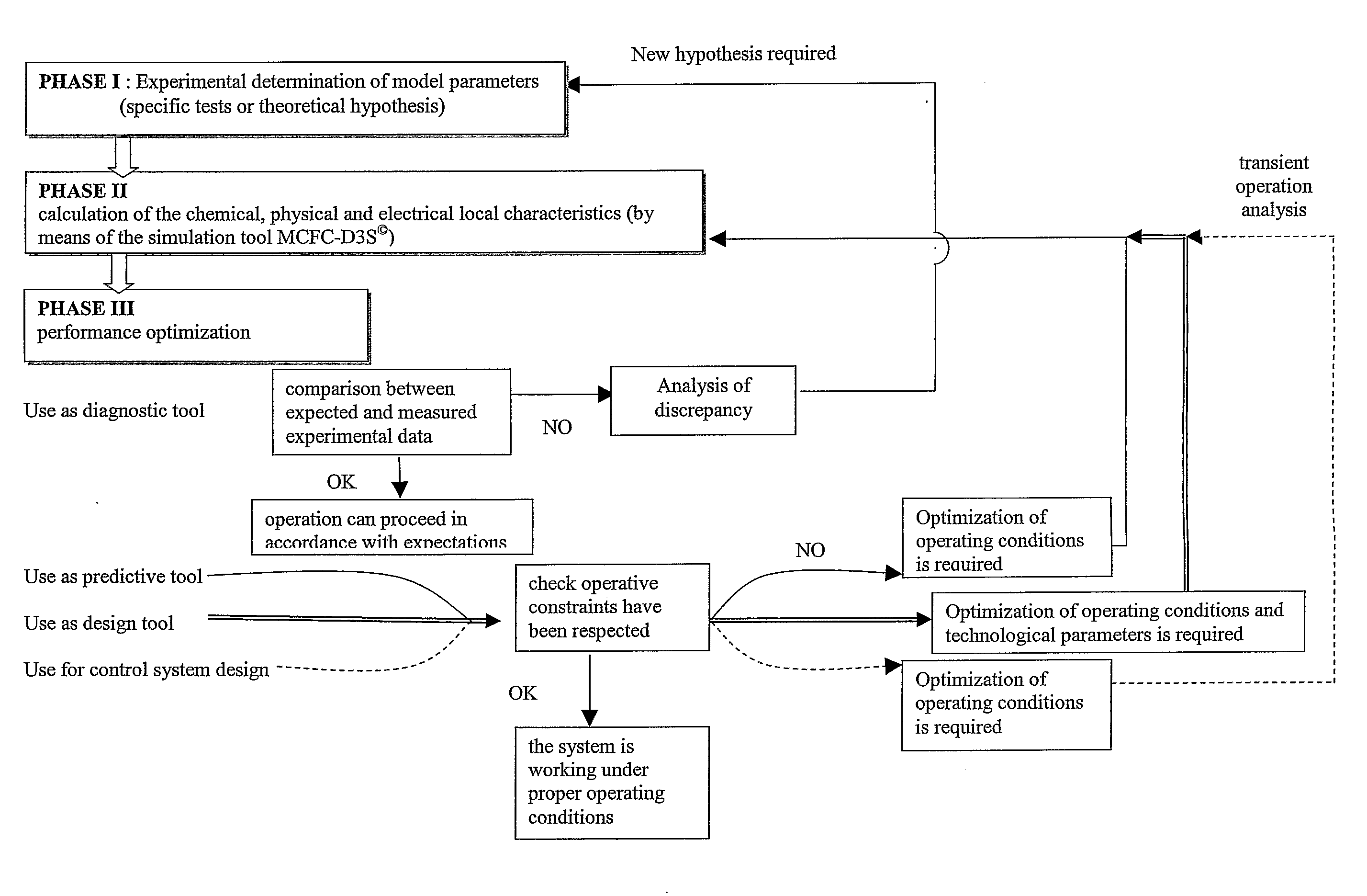
[0040]The procedure applied by the method is summarised in the flow chart on FIG. 16 and follows the scheme:

Phase 1: Evaluation of the Experimental Values

[0041]The determination of the reference experimental values relating both to the kinetic and the electrochemical characteristics of the cell is carried out on a sample cell having the same constructional properties and undergoing the same storage and w...


PUM


Abstract

A molten carbonate fuel cell stack and a method of operating a molten carbonate fuel cell stack, which fuel cell comprises a porous anode, a carbonate-comprising matrix and a porous cathode, wherein the anode section is supplied with a hydrogenous gas and the cathode section is supplied with a gaseous mixture comprising oxygen and carbon dioxide, the fuel cell is operated at a temperature in a range of about 823-973 K, with the carbonate of the carbonate-comprising matrix being in a fluid state, oxygen and carbon dioxide are reacted at the cathode, yielding carbonate ions which move from the cathode to the anode generating an electric voltage between the anode and the cathode and an electrical current circulating in the external circuit and water that has been formed is led away from the fuel cell together with carbon dioxide, comprising sampling the temperature of inlet of the reactants, sampling the temperature of outlet of reactants, sampling the current density and voltage sampling the flow rate and gas composition of the inlet and outlet gases analyzing the sampled temperature, current density, voltage flow rates and gas composition, and regulating the inlet flow rate such as the pressure drop between inlet and outlet is below 20 mbar and the temperature in each element of a cell of the stack is below 973K.

Description

FIELD OF THE INVENTION[0001]The present invention relates to fuel cells using molten carbonates as electrolyte, and, more particularly, to molten carbonate fuel cells where critical operating conditions, which can penalise electrochemical performance or cause material deterioration, are avoided by means of a proper design and operating optimisation, thereby improving their reliability.PRIOR ART[0002]A fuel cell is a power generating apparatus for converting chemical energy into electrical energy using electrochemical reactions, and is highlighted as a new promising electrical energy source because it is an environmental friendly apparatus and has a high power-generating efficiency. A fuel cell has the characteristic of continuously generating power by supplying fuel through an oxidation reaction of hydrogen and a reduction reaction of oxygen in the air. Different kinds of fuel cells are under development at the moment. In particular, the technology of molten carbonate fuel cells (MC...

Claims


Application Information

Patent Timeline
IPC IPC(8): H01M8/04H01M8/14
CPCH01M8/04298H01M8/04305Y02E60/526H01M8/244H01M2008/147H01M8/145Y02E60/50H01M8/04225
Inventor PARODI, FILIPPOBOSIO, BARBARAARATO, ELISABETTA
Owner PARODI FILIPPO
Why Eureka
Try Eureka