
Method for manufacturing semiconductor device

a semiconductor and manufacturing method technology, applied in semiconductor/solid-state device manufacturing, basic electric elements, electric devices, etc., can solve the problem of difficult pattern formation by a one-mask process with a smaller exposer resolution, and achieve the effect of improving yield and reliability of semiconductor devices

Active Publication Date: 2008-07-03
SK HYNIX INC
View PDF8 Cites 12 Cited by
  • Summary
  • Abstract
  • Description
  • Claims
  • Application Information

AI Technical Summary

Benefits of technology

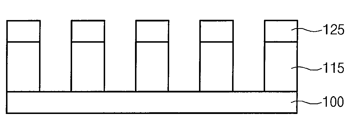
[0005]Various embodiments of the present invention relate to a method for manufacturing a semiconductor device which includes forming first photoresist patterns without forming a polysilicon layer which is a second hard mask, hardening the first photoresist patterns, and forming second photoresist patterns between the first photoresist patterns to obtain a mask pattern which has a constant height for etching an underlying layer, thereby improving yield and reliability of semiconductor devices.

Problems solved by technology

When a contact hole or a line / space pattern is formed, it is difficult to form a pattern by a one-mask process with an exposer resolution smaller than a critical dimension.

Method used


Image

  • Method for manufacturing semiconductor device
  • Method for manufacturing semiconductor device
  • Method for manufacturing semiconductor device

Examples


Embodiment Construction

[0012]The present invention will be described in detail with reference to the accompanying drawings.

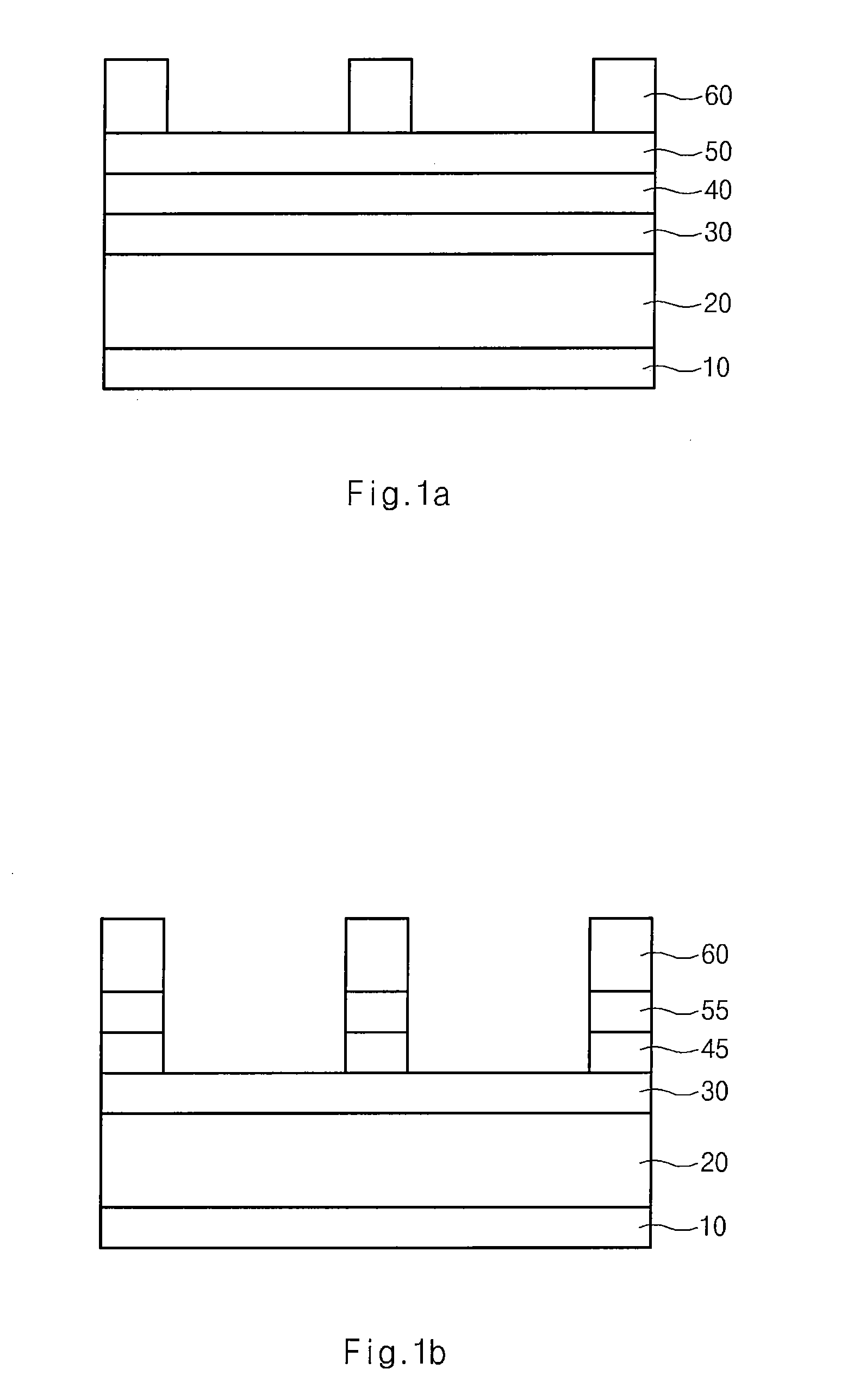
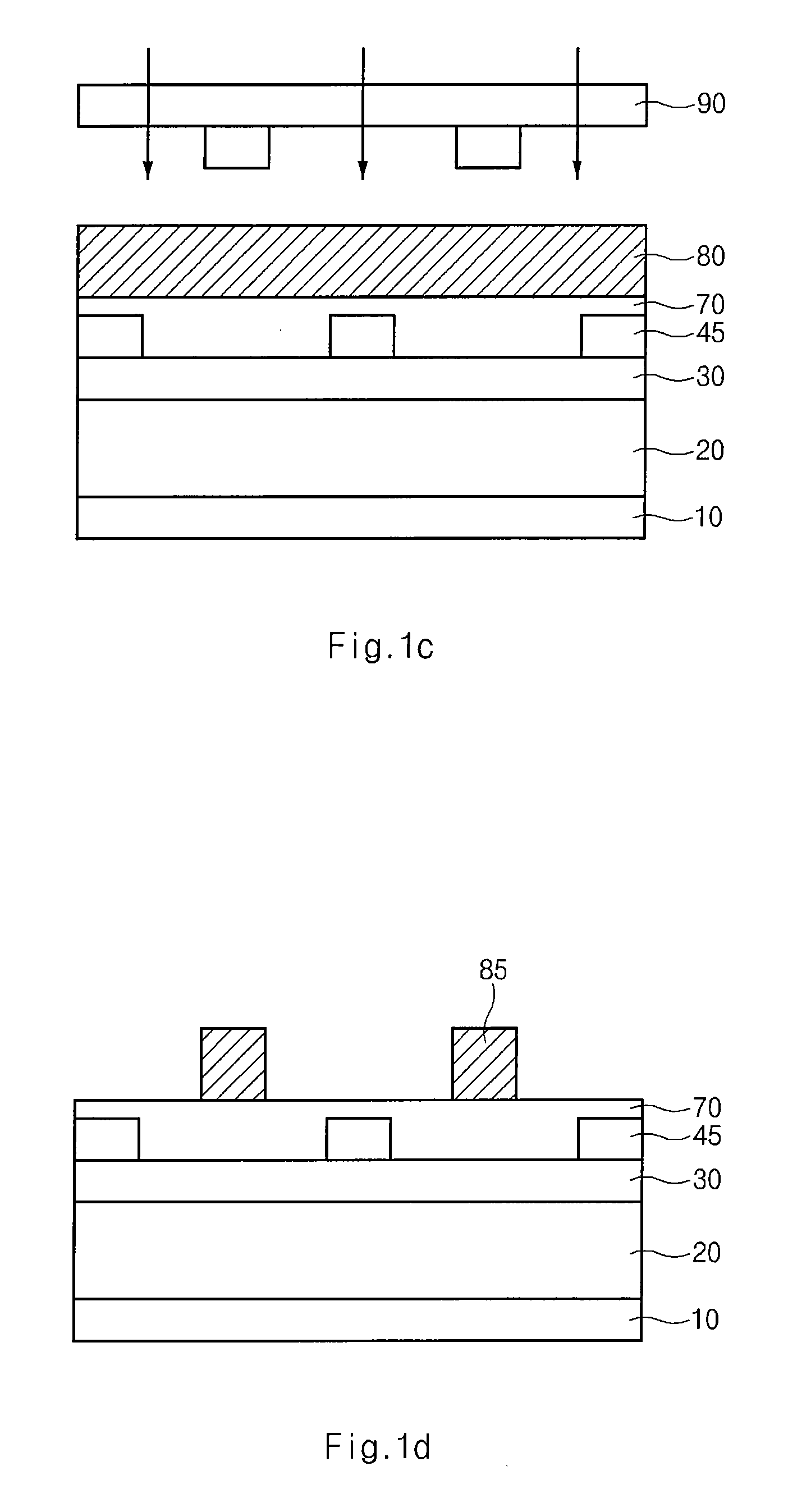
[0013]FIGS. 1a through 1g are cross-sectional diagrams illustrating a conventional double patterning process.

[0014]An underlying layer 20 is formed over a semiconductor substrate 10. A silicon oxynitride film 30, a first bottom anti-reflective coating film 40, and a polysilicon layer 50 are sequentially formed over the underlying layer 20. The silicon oxynitride film 30 is a first hard mask layer for a double patterning process, and the polysilicon layer 50 is a second hard mask layer.

[0015]A first photoresist pattern 60 is formed over the polysilicon layer 50.

[0016]The polysilicon layer 50 and the first bottom anti-reflective coating film 40 are etched with the first photoresist pattern 60 as a mask to form a polysilicon pattern 55 and a first anti-reflective pattern 45.

[0017]The first photoresist pattern 60 and the polysilicon pattern 55 are removed. A second anti-reflective coating...


PUM


Abstract

A method for manufacturing a semiconductor device includes forming an underlying layer over a semiconductor substrate; forming a hard mask layer over the underlying layer; forming first etch patterns over the hard mask layer; forming second etch patterns between the first photoresist patterns; etching the hard mask layer using the first and second etch patterns as an etch mask to form a hard mask pattern; and etching the underlying layer using at least the hard mask pattern. The first and second etch patterns are formed on the same layer.

Description

CROSS-REFERENCES TO RELATED APPLICATIONS[0001]The present application claims priority to Korean patent application number 10-2006-0136612, filed on Dec. 28, 2006, which is incorporated by reference in its entirety.BACKGROUND OF THE INVENTION[0002]The present invention relates to a semiconductor device, and more particularly, to a method for manufacturing a semiconductor device in which two or more different photoresist patterns are used for a given mask pattern.[0003]Due to high integration of semiconductor devices, the size of semiconductor devices has become smaller. As a result, the process margin for forming fine patterns is reduced.[0004]When a contact hole or a line / space pattern is formed, it is difficult to form a pattern by a one-mask process with an exposer resolution smaller than a critical dimension. As a result, a double patterning process is used with two masks. The double patterning process is performed to create fine patterns. The pattern is divided into two groups w...

Claims


Application Information

Patent Timeline
IPC IPC(8): H01L21/311
CPCH01L21/0273H01L21/31144H01L21/0338H01L21/32139
Inventor BOK, CHEOL KYU
Owner SK HYNIX INC
Learn More