Superconducting Electrical Machines

a superconducting electrical machine and superconducting technology, applied in the manufacture/treatment of superconductor devices, dynamo-electric machines, wind energy generation, etc., can solve the problems of significant source of acoustic noise, hysteresis and eddy current losses are particularly significant, so as to eliminate any stray magnetic flux and create no losses or noise.

Inactive Publication Date: 2008-07-03
LEWIS CLIVE +1
View PDF1 Cites 39 Cited by
  • Summary
  • Abstract
  • Description
  • Claims
  • Application Information

AI Technical Summary

Benefits of technology

[0021]The first rotor assembly may be directly mounted on the shaft of the superconducting electrical machine, but is preferably mounted on the shaft via a torque tube or other torque transmission arrangement. The second rotor assembly may be directly mounted on a rotor frame, but is preferably mounted on the rotor frame via a torque tube or other torque transmission arrangement. The rotor frame is in turn mounted on the shaft such that the first and second rotor assemblies rotate together. The rotor frame preferably includes a cylindrical portion to which the second rotor assembly is mounted and a radially extending portion that is fixed to the shaft. The cylindrical portion of the rotor frame can be adapted to form a rotor back iron to eliminate any stray magnetic flux. Unlike the stator iron, the rotor back iron would contain DC flux and hence creates no losses or noise.

Problems solved by technology

This core is typically laminated and contains AC flux, and hence has hysteresis and eddy current losses.
Eddy current losses are particularly significant in the end regions of superconducting machines with air gap windings.
In low speed motors, such as marine propulsion motors, the most significant source of acoustic noise is due to alternating magnetic forces action on the stator iron.
This means that the only magnetic forces acting on the stator assembly are those on the armature conductors themselves, and the rotating superconducting machine is extremely quiet.

Method used


Image

  • Superconducting Electrical Machines
  • Superconducting Electrical Machines
  • Superconducting Electrical Machines

Examples


Embodiment Construction

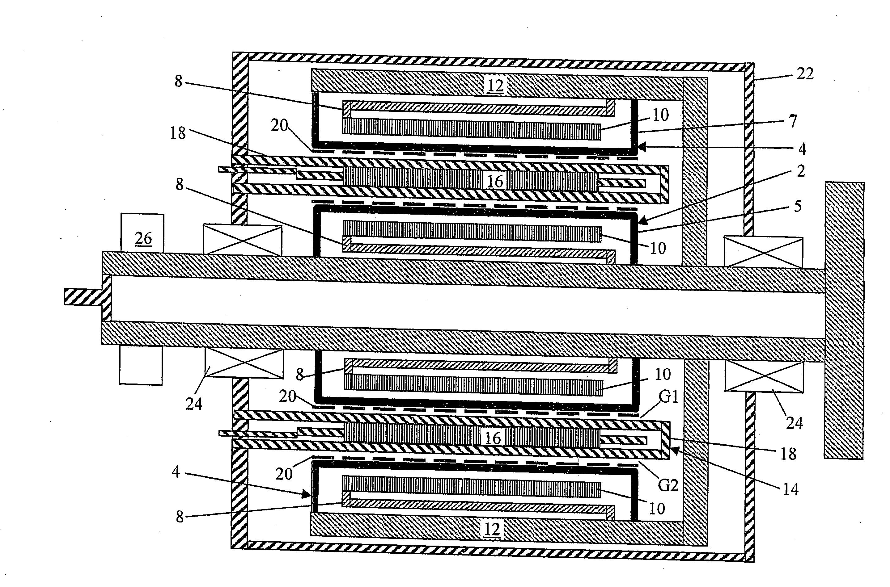
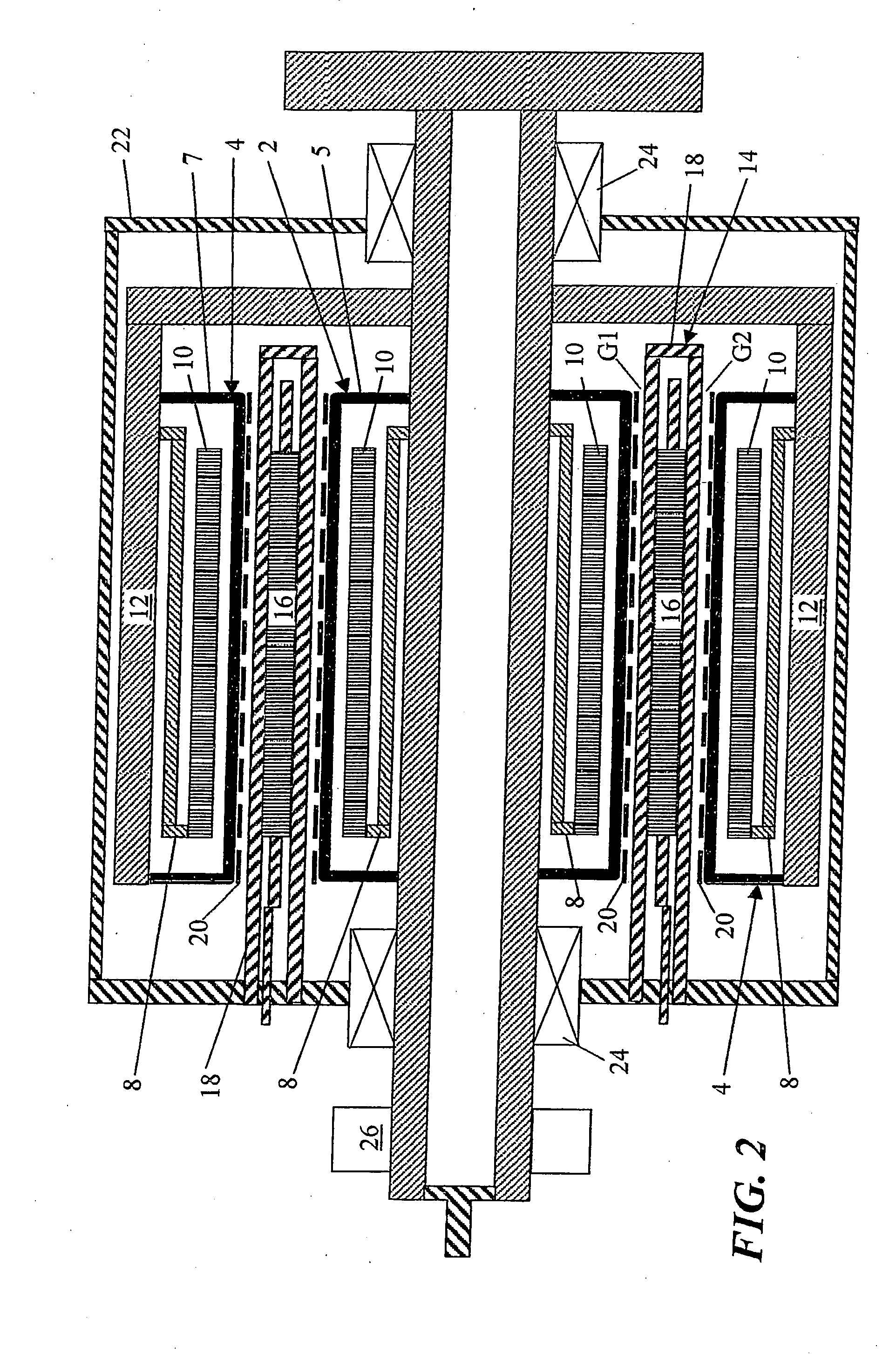
[0041]The basic structure of a machine in accordance with the invention will now be described with reference to FIGS. 2 to 5. In FIGS. 3 to 5 the prototype HTS synchronous machine has broadly the same topology as the machine shown schematically in FIG. 2. Consequently, the same reference numerals are used in FIGS. 3 to 5 to indicate machine structure that is equivalent to that shown in FIG. 2.

[0042]Referring mainly to FIG. 2, the HTS synchronous machine includes a first (radially inner) annular rotor assembly 2 and a second (radially outer) annular rotor assembly 4. The inner and outer rotor assemblies 2, 4 are enclosed by the insulated walls 5, 7 of respective annular cryogenic vacuum chambers. The walls 5 of the inner cryogenic vacuum chamber are sealingly secured to the main shaft 6, whereas the walls 7 of the outer cryogenic vacuum chamber are sealingly secured to a rotor support structure 12.

[0043]In the inner rotor assembly 2, a carrier for a number of field windings 10 is joi...


PUM

PropertyMeasurementUnit
thicknessaaaaaaaaaa
outer diameteraaaaaaaaaa

Abstract

A superconducting electrical machine has rotor and stator assemblies. A first rotor assembly is located to rotate within a stator assembly and is spaced from the stator assembly by an air gap. A second rotor assembly is located to rotate outside the stator assembly and is also spaced from the stator assembly by an air gap. The first and second rotor assemblies have at least one superconducting field winding. The superconducting field windings are formed from a High Temperature Superconducting (HTS) material such as BSCCO-2223 or YBCO, for example. The double rotor assembly configuration provides a new technical effect over conventional rotating superconducting machines having a single rotor assembly.

Description

FIELD OF THE INVENTION[0001]The present invention relates to superconducting electrical machines having rotor and stator assemblies, and in particular to such a machine that is suitable for use in applications where low speed and high torque are required in a compact size, such as wind turbine generators and marine propulsion motors.BACKGROUND OF THE INVENTION[0002]Rotating superconducting machines are well known. Early machines made use of Low Temperature Superconducting (LTS) materials such as Nb3Sn and NbTi. More recently, the development of High Temperature Superconducting (HTS) materials such as BSCCO-2223 (Bi(2-x)PbxSr2Ca2Cu10) and YBCO (YBa2Cu3O7-ε) has led to the production of rotating superconducting machines that are more practically implemented.[0003]One manufacturer from which the above-mentioned BSCCO-2223 HTS material is available is American Superconductor (AMSC), HTS Wire Manufacturing Facility of Jackson Technology Park, 64 Jackson Road, Devens, Massachussetts 01434...

Claims


Application Information

Patent Timeline
Patent Type & Authority Applications(United States)
IPC IPC(8): H02K55/04H02K16/02C04B35/45
CPCH02K16/02Y02E40/625Y02E10/725H02K55/04Y02E10/72Y02E40/60
Inventor LEWIS, CLIVELEFLEM, GRAHAM
Owner LEWIS CLIVE
Why Eureka
Try Eureka