Method and apparatus for treating or preventing a medical condition

Inactive Publication Date: 2008-07-03
WOUND SOLUTIONS LTD
View PDF40 Cites 48 Cited by
  • Summary
  • Abstract
  • Description
  • Claims
  • Application Information

AI Technical Summary

Benefits of technology

[0035]The method of treating injured tissue or preventing injury to tissue susceptible to injury or medical conditions according to the invention has the advantage that it is capable of working in combination with other treatment methods promoting the healing of wounds such as venous leg ulcers such as the application of compression bandagin

Problems solved by technology

For example, chronic wounds such as venous ulcers which form and do not heal, represent a serious problem to sufferers and healthcare providers.
The prevalence of active venous ulcers in the adult population is high and their treatment is very costly to healthcare services.
A venous ulcer is an area of damage to the skin that can occur when the vei

Method used


Image

  • Method and apparatus for treating or preventing a medical condition
  • Method and apparatus for treating or preventing a medical condition
  • Method and apparatus for treating or preventing a medical condition

Examples


first embodiment

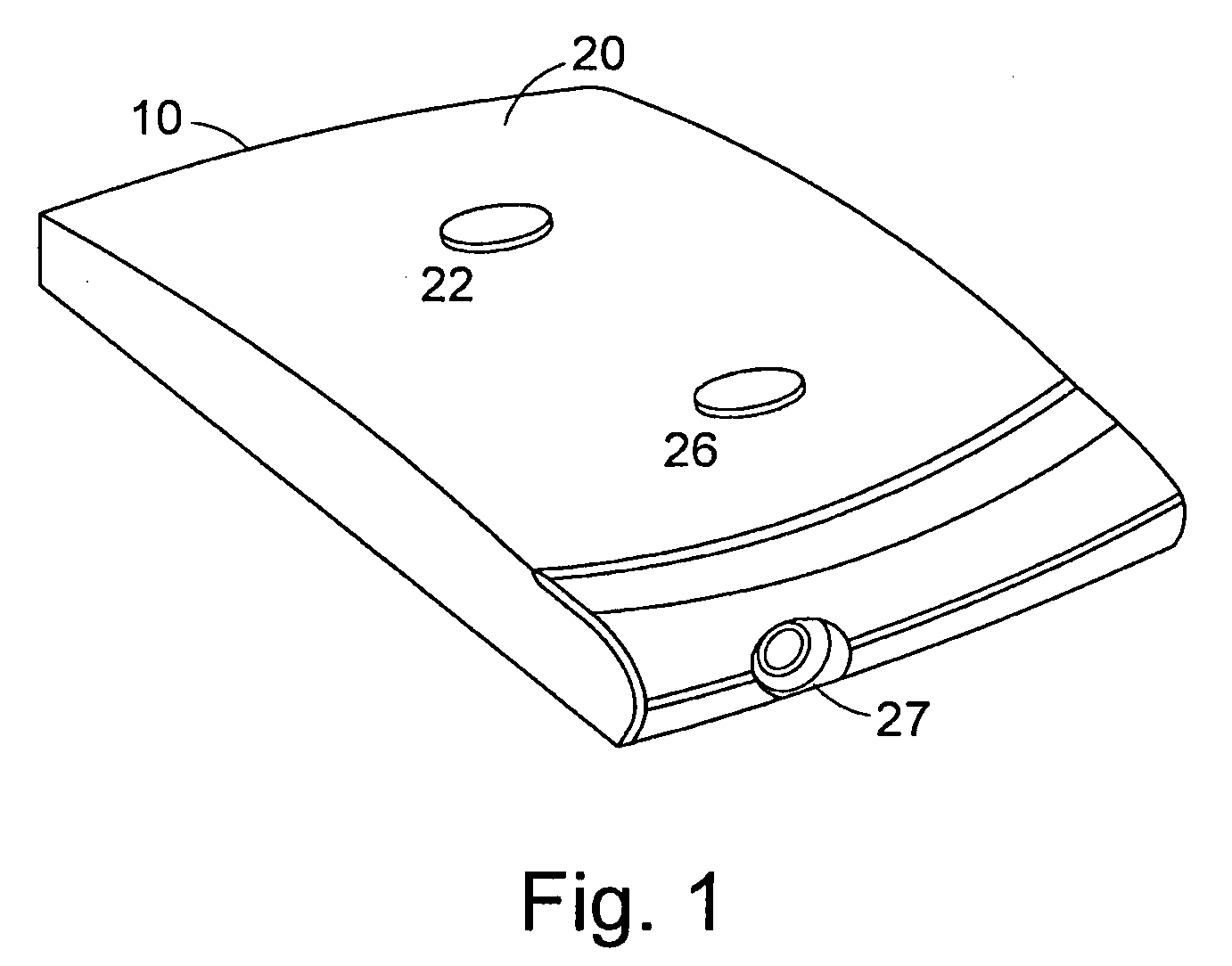
[0055]FIG. 1 is a perspective view of an electrotherapy device 10 for applying electrical signals to an area of tissue according to the present invention. The electrotherapy device 10 comprises a housing 20, a waveform generator channel having an electrode port 27, an input switch 26 and an on / off switch 22. The input switch 26 and the on / off switch 22 may be of the push button type. The housing 20 encloses the waveform generator channel 30.

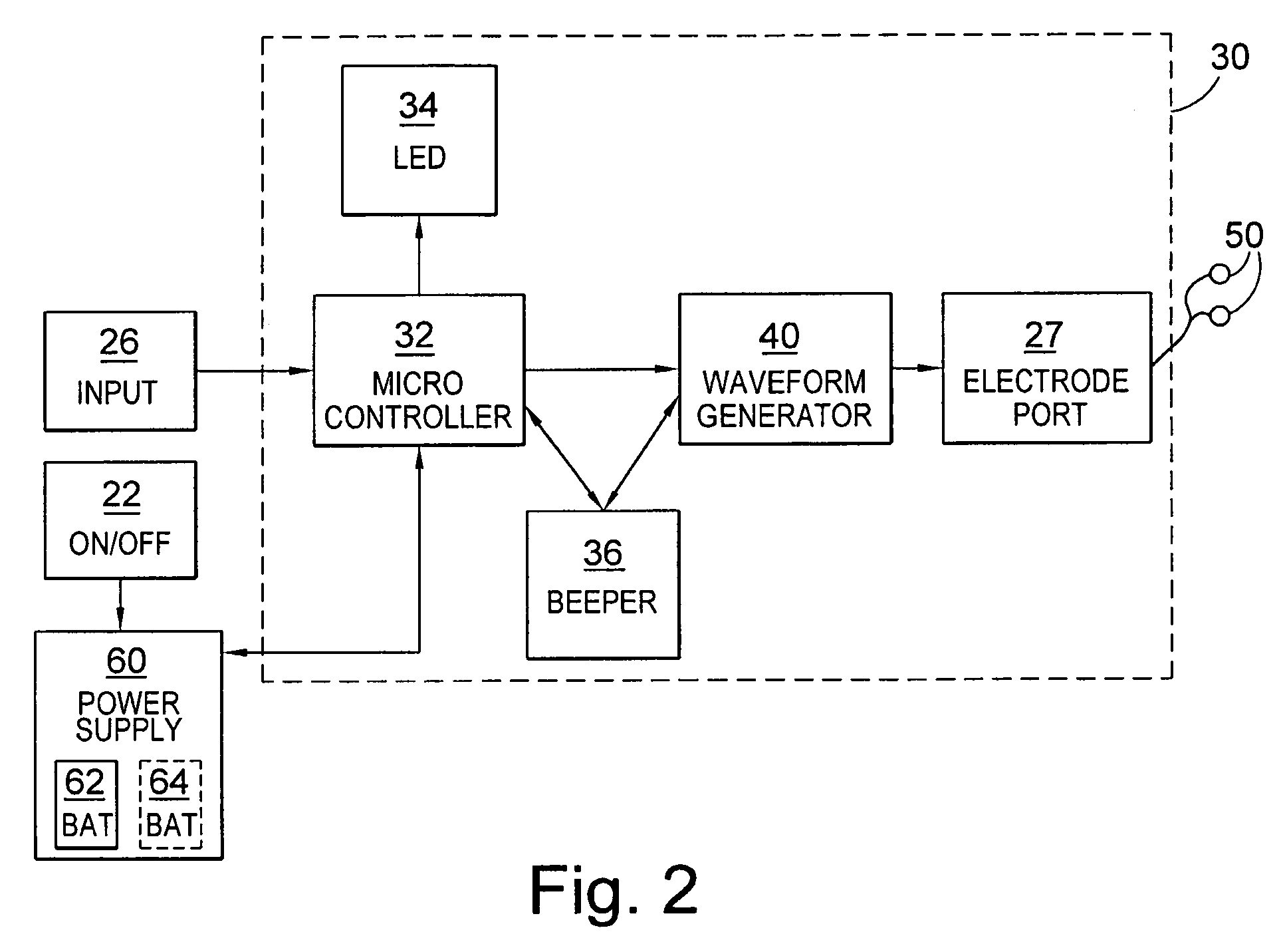
[0056]FIG. 2 is a schematic diagram of the device 10 showing the waveform generator channel 30. The channel 30 includes an electrode port 27, a microcontroller 32, a waveform generator 40, an LED unit 34 and a beeper 36. The channel 30 is connected to the input switch 26, a power supply 60 and a pair of electrodes 50. The electrodes 50 may be of any type known in the art of electrotherapy. Power supply 60 supplies the microcontroller 32 and the rest of the channel 30 with power and is controlled by on / off switch 22. In this embodiment the power s...

second embodiment

[0080]With reference to FIG. 7A, an apparatus 100 for treating an area of injured tissue according to the invention comprises two electrodes 101 and 102 formed from carbon fibre woven cable and provided on a soft fabric pad 103, electrical connectors 111 and 112 for supplying electrical signals to the electrodes 101 and 102, and an electrotherapy device 110 similar to electrotherapy device 10 of the previous embodiment, for delivering electrotherapy signals. The two electrode connectors 111 and 112 are also made of carbon fibre woven cable. Examples of such electrodes and electrode connectors are described in PCT application No. PCT / GB2007 / 000317 (published as WO 2007 / 088348) entitled “Wound Dressing”, in the name of Wound Solutions Ltd, incorporated in its entirety herewith by this specific reference thereto. The ends 171 and 172 of each connector 111 and 112, respectively, which are to be connected to the electrical generator 110, are shaped in a piercing form such that they can p...

third embodiment

[0084]an electrode arrangement for applying electrical signals to the region of treatment is illustrated in FIGS. 8A and 8B. An example of such an electrode arrangement is described in co-pending applications U.S. Ser. No. 11 / 138,358 (published as US2006173523) and U.S. Ser. No. 11 / 802,201 (published as ______) entitled “Electrode arrangement for applying electrical signals to the skin of an animal”, to Wound Solutions Ltd incorporated in their entirety herewith by this specific reference thereto. The electrode arrangement 210 comprises a flexible electrically non-conducting printed circuit board 220 with an extended portion 255 and having a first surface 221 and a second surface 222 opposed to the first surface, electrically non-conductive sealing gel 230 an electrode 240 for applying electrical signals to the skin 260 when placed in contact with the skin, and an electrically conductive connector 250 for supplying electrical signals to the electrode 240. The electrode 240 is formed...


PUM


Abstract

A method of treating a wound or preventing injury to a region susceptible to injury comprising the steps of placing a pair of electrodes placed spaced apart in the region of a wound and applying a predetermined sequence of current waveforms across the electrodes. The sequence of current waveforms comprises a first waveform comprising a series of current pulses having an amplitude in a range of from 80 to 300 μA, having a frequency in a range from 0.5 to 1.5 pulses per second and a pulse width in a range from 333 to 1000 ms, a second waveform comprising a series of current pulses having an amplitude in a range of from 20 to 60 μA, having a frequency in a range from 2 to 4 pulses per second and a pulse width in a range from 125 to 250 ms and a third waveform comprising a series of current pulses having an amplitude in a range of from 250 to 640 μA, having a frequency in a range of from 80 to 120 pulses per second and a pulse width in a range from 4 to 6 ms.

Description

CROSS REFERENCE TO RELATED APPLICATIONS[0001]The present application is a continuation-in-part of U.S. patent application Ser. No. 11 / 019,237, filed on Dec. 23, 2004 (published as US2006142817A1).[0002]Related patent applications U.S. Ser. No. 11 / 138,358 (published as US2006173523A1), and U.S. Ser. No. 11 / 802,201, International applications PCT / GB2006 / 00315 (published as WO2006082384), PCT / GB2007 / 00317 (published as WO 2007 / 088348) and PCT / GB2007 / 01842 (published as WO 2008 / 003920) are incorporated in their entirety herein by reference thereto. UK patent application GBO701129.9 is incorporated by reference.FIELD OF THE INVENTION[0003]The present invention generally relates to a method and apparatus for treating or preventing a medical condition. In particular, the invention relates to a method and apparatus for treating an area of injured tissue such as a wound, or for preventing injury to tissue susceptible to injury, such as the formation of a wound, involving application of elect...

Claims


Application Information

Patent Timeline
IPC IPC(8): A61N1/32A61N2/04A61N7/00A61F5/00
CPCA61N1/0468A61N1/0476A61N1/32A61N1/0492A61N1/08A61N1/048A61N1/3603
Inventor CHANDLER, MARKMORETTI, ANDREANAGLE, RICHARDRAINEY, CHRISTOPHER JOHNSOUTHGATE, JOHN PETER
Owner WOUND SOLUTIONS LTD
Why Eureka
Try Eureka